Chapter 2
SNVU166 – FEBRUARY 2013
EVM Configuration and Description
2.1
EVM Options
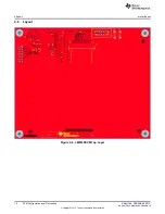
The hardware is based on the TI MSP430 16-bit, ultra-low power, mixed signal micro-controller with
integrated USB. The PCB is a four-layer board with components mounted on both top and bottom layers
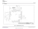
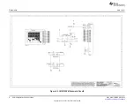
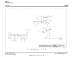
(refer to SCHEMATIC).
2.2
LED (D1) Indication of USB Attached
A green LED is mounted adjacent to the USB (J3) connector on the EVM. Every time the USB interface
adapter is attached to a PC via a USB cable, and if the host PC detects it and goes through enumeration
successfully, the embedded firmware illuminates the LED (D1); otherwise, the LED remains off. After
unplugging the USB cable, the LED turns off immediately.
2.3
Input/Output Connector Description
J2 - Input/Output is the keypad IO connector. This connector provides the connection between the keypad
and the LM8330.
J3 - Input is the USB input connector. This connector provides USB data communication, 5V Power In and
ground (GND) connections.
J4 - Input/Output is the I
2
C input/output connector. This connector provides access to the I
2
C SCL and
SDA signals for monitoring from an external device.
2.4
Test Point Connectors
Test point connectors TP1 through TP4 allow the users to verify internal power rails on the LM8330EVM.
describes the functions of all of the test points on the EVM.
Table 2-1. Test Point Descriptions
Test Point
Signal
Functionality
Connect to DMM positive terminal to monitor the LM8330 1.8V power
TP1
1.8V Test Point
rail
Connect to DMM negative terminal to monitor the LM8330 1.8V power
TP2
GND Test Point
rail
Connect to DMM negative terminal to monitor the LM8330 3.3V power
TP3
GND Test Point
rail
Connect to DMM positive terminal to monitor the LM8330 3.3V power
TP4
3.3V Test Point
rail
6
EVM Configuration and Description
SNVU166 – FEBRUARY 2013
Copyright © 2013, Texas Instruments Incorporated


