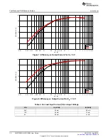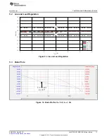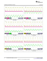
I
OUT
(A)
EFFIC
IE
N
C
Y (%
)
0
1
2
3
4
5
6
88
90
92
94
96
98
100
D001
V
IN
= 6V
V
IN
= 12V
V
IN
= 18V
V
IN
= 24V
V
IN
= 30V
V
IN
= 36V
Test Setup and Procedure
8
SNVU518 – April 2016
Copyright © 2016, Texas Instruments Incorporated
LM5175RHF (QFN) EVM User Guide
4.3
Test Procedure
4.3.1
Line, Load Regulation and Efficiency
•
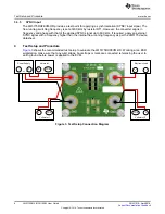
Set up the EVM as described above.
•
Set target load in the electronic load using either constant resistance or constant current mode.
•
Increase input source from 0 V to 42 V, using voltmeter 1 to measure input voltage.
•
Use voltmeter 2 to measure output voltage, V
OUT
.
•
Vary load from 0 to 6 Adc, V
OUT
should remain within load regulation specification.
•
Vary input source voltage from 5.5 V to 42 V, V
OUT
should remain within line regulation specification.
•
Decrease load to 0 A. Decrease input source voltage to 0 V to power down.
4.3.2
Control Loop Gain and Phase
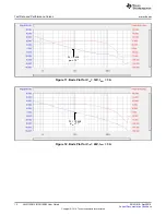
The resistor R16 on the LM5175RHFEVM-HD is a convenient injection point for loop response analysis.
•
Set up EVM as described previously.
•
Connect isolation transformer secondary across R16.
•
Connect output signal amplitude measurement probe (TEST) to VOUT and input signal amplitude
measurement (REF) probe to opposite side of R16.
•
Connect ground leads to the AGND test point as required.
•
Apply 10 mV or less AC signal to the isolation transformer primary. Adjust amplitude as necessary.
•
Sweep the frequency over the frequency range of interest (e.g. 100 Hz to 100 kHz) with 10 Hz or lower
post filter.
•
Measure the control loop gain and phase characteristic. Record the crossover frequency and phase
margin.
•
Disconnect isolation transformer before making other measurements (signal injection into the loop may
interfere with the integrity of other measurements).
5
Test Data and Performance Curves
5.1
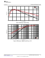
Efficiency
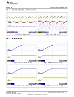
Figure 4. Efficiency vs. Output Current


