www.ti.com
Schematic, PCB Layout, and Bill of Materials
9
SBOU167 – March 2019
Submit Documentation Feedback
Copyright © 2019, Texas Instruments Incorporated
INA185EVM
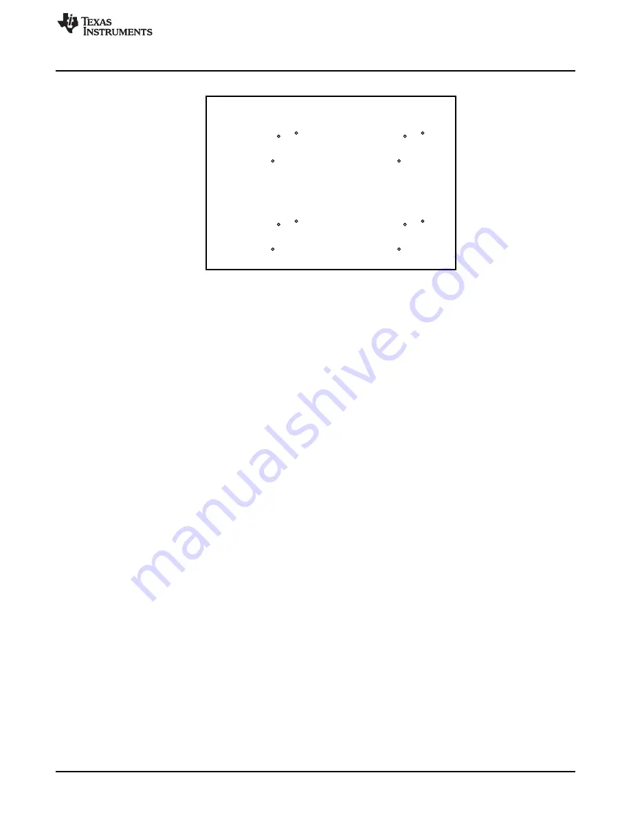
Figure 8. INA185EVM Drill Drawing
Страница 1: ...e INA185 evaluation module EVM This EVM is designed to evaluate the performance of the INA185A1 INA185A2 INA185A3 and INA185A4 voltage output current shunt monitors in a variety of configurations Thro...
Страница 2: ...Bill of Materials 7 List of Figures 1 INA185EVM Schematic 7 2 INA185EVM Top Overlay 8 3 INA185EVM Bottom Overlay 8 4 INA185EVM Top Solder Mask 8 5 INA185EVM Top Layer 8 6 INA185EVM Bottom Layer 8 7 I...
Страница 3: ...the contents of the INA185EVM kit Contact the nearest Texas Instruments Product Information Center if any components are missing TI highly recommends checking the INA185 family product folder on the T...
Страница 4: ...devices with the INA185EVM For the circuits in the following instructions x A to D Step 1 Connect an external dc supply voltage between 2 7 V and 5 5 V to the VCC test point TP2x and connect the groun...
Страница 5: ...R3x TP4x and TP5x C3x and R3x form a low pass filter on the output of the INA185 U1x By default no filter is installed with R3x shorted by a 0 resistor and C6x not populated TP4x shows unfiltered out...
Страница 6: ...e REF pin The voltage applied to REF sets the output state that corresponds to the zero input level state The output then responds by increasing to greater than REF for positive differential signals r...
Страница 7: ...ot intended to be used for manufacturing INA185EVM PCBs 6 1 Schematic Figure 1 shows the schematic for the INA185EVM PCB Only the schematic for the 20 V V gain variant is included because all other va...
Страница 8: ...xas Instruments Incorporated INA185EVM 6 2 PCB Layout Figure 2 through Figure 8 illustrate the PCB layout for the INA185EVM Figure 2 INA185EVM Top Overlay Figure 3 INA185EVM Bottom Overlay Figure 4 IN...
Страница 9: ...www ti com Schematic PCB Layout and Bill of Materials 9 SBOU167 March 2019 Submit Documentation Feedback Copyright 2019 Texas Instruments Incorporated INA185EVM Figure 8 INA185EVM Drill Drawing...
Страница 10: ...TP7A TP7B TP7C TP7D TP8A TP8B TP8C TP8D TP9A TP9B TP9C TP9D 36 Test Point Miniature SMT Testpoint_Keystone_Miniature 5015 Keystone U1A 1 Bidirectional Precision Low and High Side Voltage Output Curren...
Страница 11: ...ther than TI b the nonconformity resulted from User s design specifications or instructions for such EVMs or improper system design or c User has not paid on time Testing and other quality control tec...
Страница 12: ...These limits are designed to provide reasonable protection against harmful interference in a residential installation This equipment generates uses and can radiate radio frequency energy and if not in...
Страница 13: ...instructions set forth by Radio Law of Japan which includes but is not limited to the instructions below with respect to EVMs which for the avoidance of doubt are stated strictly for convenience and s...
Страница 14: ...any interfaces electronic and or mechanical between the EVM and any human body are designed with suitable isolation and means to safely limit accessible leakage currents to minimize the risk of electr...
Страница 15: ...R DAMAGES ARE CLAIMED THE EXISTENCE OF MORE THAN ONE CLAIM SHALL NOT ENLARGE OR EXTEND THIS LIMIT 9 Return Policy Except as otherwise provided TI does not offer any refunds returns or exchanges Furthe...
Страница 16: ...e resources are subject to change without notice TI grants you permission to use these resources only for development of an application that uses the TI products described in the resource Other reprod...