Using the Software
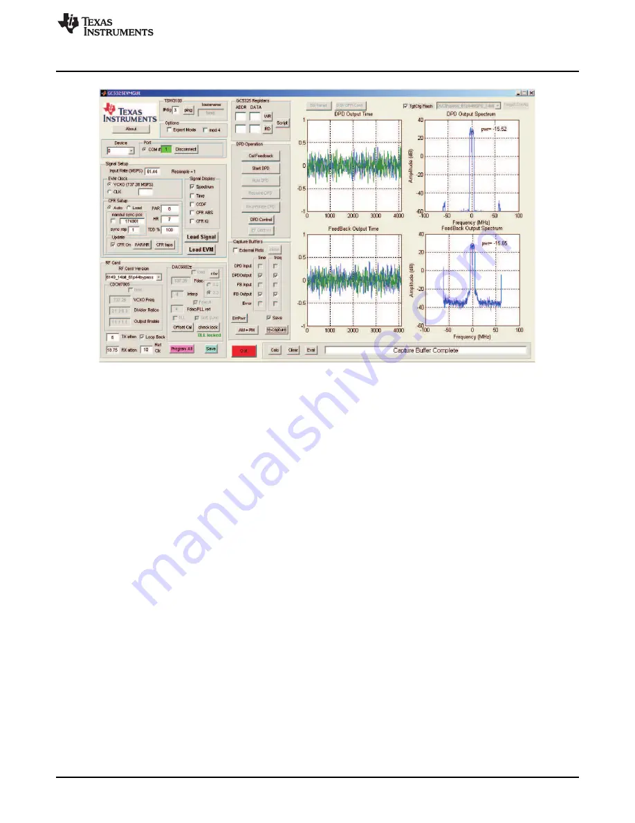
Figure 18. Loopback Results Using GC5325 Internal Capture Buffers
To view the DPD input, FB input, or Error capture buffers, the external plots check box needs to be
checked. This opens the plots in separate windows. This is also useful if separate performance plots
are needed for reports.
Both channels must be calibrated before starting DPD. Change the GUI device setting from "0" to "1"
and repeat steps a-c. After Channel 1 has been calibrated, the user can now run DPD on Channel 0,
Channel 1, or both at the same time. Change the GUI device setting from "1" to "0"
2. Start DPD by clicking on Start DPD. Once DPD starts, the system continues to adapt until the Hold
DPD command is issued. All buttons except for Hold DPD and Re-initialize DPD are disabled.. To do
any action such as capturing buffers, reloading the DSP/GC5322, etc., the user must click the Hold
DPD button. If both channels are running DPD, both channels must be in the Hold DPD state to enable
the other functional buttons.
Click on the Hold DPD button. Click on the "re-capture" button. After the capture has been completed,
the status window displays Capture Buffer Complete, and the GUI now looks as shown in
.
The DPD output buffer and the Feedback buffer reflect the DPD operation on the internal loopback PA.
19
SLWU063F
–
April 2009
–
Revised April 2011
GC5325 System Evaluation Kit
Copyright
©
2009
–
2011, Texas Instruments Incorporated


