


Hardware Installation
10
SLAU647L – July 2015 – Revised February 2018
Copyright © 2015–2018, Texas Instruments Incorporated
MSP Debuggers
4.4
Hardware Installation Using the MSP Flasher
MSP Flasher is an open-source shell-based interface for programming any MSP430 device through a
and provides the most common functions on the command line. MSP Flasher can be
used to download binary files (.txt or .hex) directly to the MSP430 memory without the need for an IDE like
CCS or IAR. It can also be used to extract firmware directly from a device, set hardware breakpoints, and
lock JTAG access permanently.
MSP Flasher supports the following operating systems:
•
Windows 10 32-bit or 64-bit
•
Windows 8 32-bit or 64-bit
•
Windows 7 32-bit or 64-bit
•
Windows XP 32-bit or 64-bit
•
Ubuntu™ 32-bit or 64-bit
•
OS X 64-bit
Installation steps for the MSP-FET430UIF, MSP-FET, eZ-FET or eZ-FET Lite:
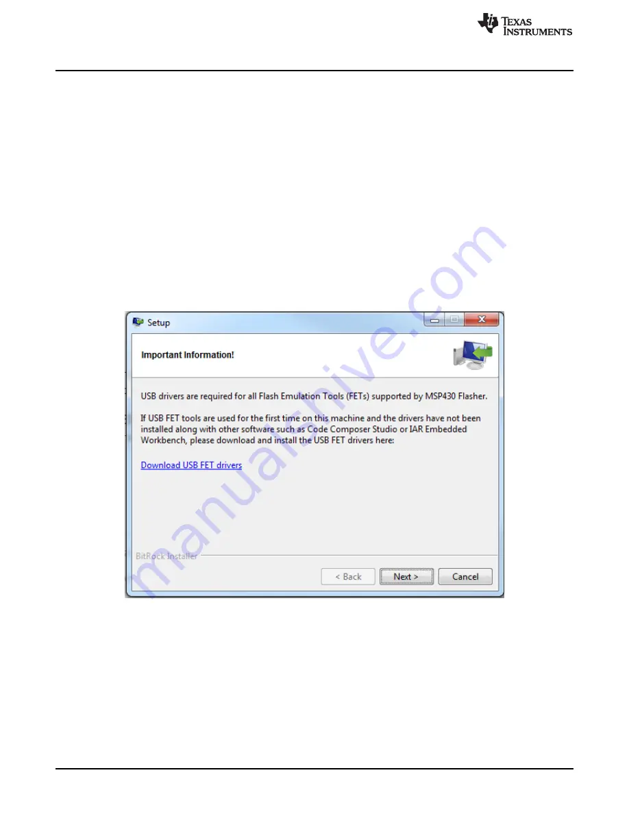
1. After successfully downloading and executing the MSP Flasher installer, it prompts you to execute the
for the MSP debug probes.
Figure 6. MSP Flasher Driver Install Notification
2. Follow the steps given by the stand-alone driver installer for debug probe driver installation.
3. After successful driver installation, connect the debug probe to a USB port on the PC using the
provided USB cable.
4. After connecting the debug probe to a PC, it performs a self-test. If the self-test passes, the green LED
stays on. For a complete list of LED signals, see the
LED Signals
section of every debug probe in
through
.
5. Connect the debug probe with the target board using the 14-pin ribbon cable.
6. When using a target socket board, make sure that the MSP430 device is properly inserted in the
socket and that its pin 1 (indicated with a circular indentation on the top surface) aligns with the "1"
mark on the PCB.


