
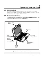


Theory of Operation
4-3
4.2.1 System Processor
The System Processor function for the notebook is implemented on the System Board
in the form of an Intel Pentium P55CLM 166 MHz Super scalar 586 Processor Chip.
The processor operates in conjunction with RAM and ROM Memory and other control
logic to process software instructions (BIOS, DOS, Windows, and applications). The
processor communicates with the hard disk drive and the memory components using
high speed busses.
The Processor also interacts with other hardware logic to provide the power savings
features for the notebook. These features include controlling CPU clock speeds,
reducing clock speeds whenever possible, e.g., when performing floppy disk drive
accesses, powering down unused devices, etc.
4.2.2
Memory Subsystem
The memory subsystem comprises the following components:
♦
Main memory
♦
L2 Secondary Memory (cache)
♦
Flash ROM
The Extensa Series uses fast Extended Data Out (EDO) DRAM for main and video
memory and high-speed synchronous, pipelined burst SRAM for L2 cache memory.
Main BIOS and Video BIOS are stored in Flash ROM.
4.2.2.1 Main Memory
The standard 660 Series notebook comes with 16 MB of Main memory installed on the
System Board. Memory expansion accommodations are provided via a standard
soDIMM connector on the bottom of the System Board Assembly. By installing a
64 MB soDIMM module, the basic memory size can be expanded to a maximum of
80 MB.
4.2.2.2 Flash ROM
All versions of the Extensa notebook family use a "Flash" ROM that contains both the
main system BIOS and the VGA BIOS. The Flash ROM contains "Boot Block" logic
that allows downloading new versions of BIOS without destroying the Boot Load area.
The Flash ROM execution RAM is 8 bits wide. However, better performance is attained
by enabling the Shadow. With this feature enabled, BIOS is copied into a 32-bit, high-
speed system.
4.2.3 System Controller Function
The system controller function is implemented on the System Board via a UMC 8890
Series Notebook Chipset. The UM8890 is an advanced 586 compatible single chip that
integrates such functions as the PMU, System Controller, RTC and Peripheral
Содержание Extensa 660 Series
Страница 1: ...Maintenance Manual ExtensaTM 660 Series Notebook Computers 9813214 0001 Rev A February 1997 ...
Страница 42: ......
Страница 60: ......
Страница 94: ......
Страница 122: ......
Страница 124: ...A 2 Schematic Diagrams Figure A 1 Motherboard PWB Logic Diagrams Sheet 1 of 23 ...
Страница 125: ...Schematic Diagrams A 3 Figure A 2 Motherboard PWB Logic Diagrams Sheet 2 of 23 ...
Страница 126: ...A 4 Schematic Diagrams Figure A 1 Motherboard PWB Logic Diagrams Sheet 3 of 23 ...
Страница 127: ...Schematic Diagrams A 5 Figure A 1 Motherboard PWB Logic Diagrams Sheet 4 of 23 ...
Страница 128: ...A 6 Schematic Diagrams Figure A 1 Motherboard PWB Logic Diagrams Sheet 5 of 23 ...
Страница 129: ...Schematic Diagrams A 7 Figure A 1 Motherboard PWB Logic Diagrams Sheet 6 of 23 ...
Страница 130: ...A 8 Schematic Diagrams Figure A 1 Motherboard PWB Logic Diagrams Sheet 7 of 23 ...
Страница 131: ...Schematic Diagrams A 9 Figure A 1 Motherboard PWB Logic Diagrams Sheet 8 of 23 ...
Страница 132: ...A 10 Schematic Diagrams Figure A 1 Motherboard PWB Logic Diagrams Sheet 9 of 23 ...
Страница 133: ...Schematic Diagrams A 11 Figure A 1 Motherboard PWB Logic Diagrams Sheet 10 of 23 ...
Страница 134: ...A 12 Schematic Diagrams Figure A 1 Motherboard PWB Logic Diagrams Sheet 11 of 23 ...
Страница 135: ...Schematic Diagrams A 13 Figure A 1 Motherboard PWB Logic Diagrams Sheet 12 of 23 ...
Страница 136: ...A 14 Schematic Diagrams Figure A 1 Motherboard PWB Logic Diagrams Sheet 13 of 23 ...
Страница 137: ...Schematic Diagrams A 15 Figure A 1 Motherboard PWB Logic Diagrams Sheet 14 of 23 ...
Страница 138: ...A 16 Schematic Diagrams Figure A 1 Motherboard PWB Logic Diagrams Sheet 15 of 23 ...
Страница 139: ...Schematic Diagrams A 17 Figure A 1 Motherboard PWB Logic Diagrams Sheet 16 of 23 ...
Страница 140: ...A 18 Schematic Diagrams Figure A 1 Motherboard PWB Logic Diagrams Sheet 17 of 23 ...
Страница 141: ...Schematic Diagrams A 19 Figure A 1 Motherboard PWB Logic Diagrams Sheet 18 of 23 ...
Страница 142: ...A 20 Schematic Diagrams Figure A 1 Motherboard PWB Logic Diagrams Sheet 19 of 23 ...
Страница 143: ...Schematic Diagrams A 21 Figure A 1 Motherboard PWB Logic Diagrams Sheet 20 of 23 ...
Страница 144: ...A 22 Schematic Diagrams Figure A 1 Motherboard PWB Logic Diagrams Sheet 21 of 23 ...
Страница 145: ...Schematic Diagrams A 23 Figure A 1 Motherboard PWB Logic Diagrams Sheet 22 of 23 ...
Страница 146: ...A 24 Schematic Diagrams Figure A 1 Motherboard PWB Logic Diagrams Sheet 23 of 23 ...
Страница 147: ......