2-4
Installation
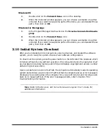
In Windows 95
Follow these steps if your computer is running Windows 95.
1.
From the Taskbar, select
Start
then
Shut Down
.
2.
Select the
Restart the Computer in MS-DOS mode
.
3.
Click on
Yes
.
4.
Type
PHDISK /C /F
at the DOS prompt and press
Enter
.
5.
The DOS screen appears and shows the save file name and size. Press any
key to reset the system. The computer will reboot.
In Windows for Workgroups
Follow these steps if your computer is running MS-DOS and Windows for Workgroups.
1.
Close all applications and exit Windows for Workgroups to MS-DOS.
2.
At the command prompt (typically C:\) type
PHDISK /C /F
and press
Enter
.
This will create a file which can be used to save the contents of your memory
system when you perform a
0V Suspend
operation.
2.3.3 Installing Advanced PCI Option Card
To install an Advanced PCI Card option, use the following procedure:
Caution: The Advanced PCI card option contains components that are
sensitive to static electricity. When handling the card and the internal
parts of the computer, protect against static electricity by using wrist or
ankle grounding straps and grounded working mats. When moving or
storing items, use the anti-static bags supplied with the items.
1.
Ensure that the notebook is powered off and the AC adapter disconnected
from the AC outlet. Also, ensure that the battery is out of the unit.
2.
Disconnect any peripheral device interface cables from the external interface
connectors and remove any installed PCMCIA options.
3.
Turn the notebook over and locate the Advanced PCI Access Cover on the
bottom of the notebook (refer to Figure 2-2).
4.
Remove the screw holding the Advanced PCI Access Cover and remove the
cover.
5.
Review the installation instructions supplied with the Advanced PCI option
card.
6.
Hold the card at the end opposite the connector pins with the label side up.
Insert the card firmly into the Advanced PCI connector on the Main Board.
Содержание Extensa 660 Series
Страница 1: ...Maintenance Manual ExtensaTM 660 Series Notebook Computers 9813214 0001 Rev A February 1997 ...
Страница 42: ......
Страница 60: ......
Страница 94: ......
Страница 122: ......
Страница 124: ...A 2 Schematic Diagrams Figure A 1 Motherboard PWB Logic Diagrams Sheet 1 of 23 ...
Страница 125: ...Schematic Diagrams A 3 Figure A 2 Motherboard PWB Logic Diagrams Sheet 2 of 23 ...
Страница 126: ...A 4 Schematic Diagrams Figure A 1 Motherboard PWB Logic Diagrams Sheet 3 of 23 ...
Страница 127: ...Schematic Diagrams A 5 Figure A 1 Motherboard PWB Logic Diagrams Sheet 4 of 23 ...
Страница 128: ...A 6 Schematic Diagrams Figure A 1 Motherboard PWB Logic Diagrams Sheet 5 of 23 ...
Страница 129: ...Schematic Diagrams A 7 Figure A 1 Motherboard PWB Logic Diagrams Sheet 6 of 23 ...
Страница 130: ...A 8 Schematic Diagrams Figure A 1 Motherboard PWB Logic Diagrams Sheet 7 of 23 ...
Страница 131: ...Schematic Diagrams A 9 Figure A 1 Motherboard PWB Logic Diagrams Sheet 8 of 23 ...
Страница 132: ...A 10 Schematic Diagrams Figure A 1 Motherboard PWB Logic Diagrams Sheet 9 of 23 ...
Страница 133: ...Schematic Diagrams A 11 Figure A 1 Motherboard PWB Logic Diagrams Sheet 10 of 23 ...
Страница 134: ...A 12 Schematic Diagrams Figure A 1 Motherboard PWB Logic Diagrams Sheet 11 of 23 ...
Страница 135: ...Schematic Diagrams A 13 Figure A 1 Motherboard PWB Logic Diagrams Sheet 12 of 23 ...
Страница 136: ...A 14 Schematic Diagrams Figure A 1 Motherboard PWB Logic Diagrams Sheet 13 of 23 ...
Страница 137: ...Schematic Diagrams A 15 Figure A 1 Motherboard PWB Logic Diagrams Sheet 14 of 23 ...
Страница 138: ...A 16 Schematic Diagrams Figure A 1 Motherboard PWB Logic Diagrams Sheet 15 of 23 ...
Страница 139: ...Schematic Diagrams A 17 Figure A 1 Motherboard PWB Logic Diagrams Sheet 16 of 23 ...
Страница 140: ...A 18 Schematic Diagrams Figure A 1 Motherboard PWB Logic Diagrams Sheet 17 of 23 ...
Страница 141: ...Schematic Diagrams A 19 Figure A 1 Motherboard PWB Logic Diagrams Sheet 18 of 23 ...
Страница 142: ...A 20 Schematic Diagrams Figure A 1 Motherboard PWB Logic Diagrams Sheet 19 of 23 ...
Страница 143: ...Schematic Diagrams A 21 Figure A 1 Motherboard PWB Logic Diagrams Sheet 20 of 23 ...
Страница 144: ...A 22 Schematic Diagrams Figure A 1 Motherboard PWB Logic Diagrams Sheet 21 of 23 ...
Страница 145: ...Schematic Diagrams A 23 Figure A 1 Motherboard PWB Logic Diagrams Sheet 22 of 23 ...
Страница 146: ...A 24 Schematic Diagrams Figure A 1 Motherboard PWB Logic Diagrams Sheet 23 of 23 ...
Страница 147: ......


