Installation
2-3
Figure 2-1 Memory Expansion Removal/Replacement
Note:
After installing expansion memory in your notebook, you must run the
PHDISK
utility in order for the
Save-To-Disk
or
0V Suspend
functions to operate
correctly.
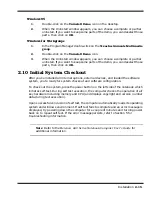
2.3.2 Setting up the Software
Note:
If you are using an operating system other than Windows 95, Windows for
Workgroups, or DOS, you may need to re-partition your hard disk drive to allow
for the additional memory. Check with your system administrator.
Memory Expansion
Compartment With
Cover Removed
soDIMM
Socket
Installing soDIMM
in Socket
Содержание Extensa 660 Series
Страница 1: ...Maintenance Manual ExtensaTM 660 Series Notebook Computers 9813214 0001 Rev A February 1997 ...
Страница 42: ......
Страница 60: ......
Страница 94: ......
Страница 122: ......
Страница 124: ...A 2 Schematic Diagrams Figure A 1 Motherboard PWB Logic Diagrams Sheet 1 of 23 ...
Страница 125: ...Schematic Diagrams A 3 Figure A 2 Motherboard PWB Logic Diagrams Sheet 2 of 23 ...
Страница 126: ...A 4 Schematic Diagrams Figure A 1 Motherboard PWB Logic Diagrams Sheet 3 of 23 ...
Страница 127: ...Schematic Diagrams A 5 Figure A 1 Motherboard PWB Logic Diagrams Sheet 4 of 23 ...
Страница 128: ...A 6 Schematic Diagrams Figure A 1 Motherboard PWB Logic Diagrams Sheet 5 of 23 ...
Страница 129: ...Schematic Diagrams A 7 Figure A 1 Motherboard PWB Logic Diagrams Sheet 6 of 23 ...
Страница 130: ...A 8 Schematic Diagrams Figure A 1 Motherboard PWB Logic Diagrams Sheet 7 of 23 ...
Страница 131: ...Schematic Diagrams A 9 Figure A 1 Motherboard PWB Logic Diagrams Sheet 8 of 23 ...
Страница 132: ...A 10 Schematic Diagrams Figure A 1 Motherboard PWB Logic Diagrams Sheet 9 of 23 ...
Страница 133: ...Schematic Diagrams A 11 Figure A 1 Motherboard PWB Logic Diagrams Sheet 10 of 23 ...
Страница 134: ...A 12 Schematic Diagrams Figure A 1 Motherboard PWB Logic Diagrams Sheet 11 of 23 ...
Страница 135: ...Schematic Diagrams A 13 Figure A 1 Motherboard PWB Logic Diagrams Sheet 12 of 23 ...
Страница 136: ...A 14 Schematic Diagrams Figure A 1 Motherboard PWB Logic Diagrams Sheet 13 of 23 ...
Страница 137: ...Schematic Diagrams A 15 Figure A 1 Motherboard PWB Logic Diagrams Sheet 14 of 23 ...
Страница 138: ...A 16 Schematic Diagrams Figure A 1 Motherboard PWB Logic Diagrams Sheet 15 of 23 ...
Страница 139: ...Schematic Diagrams A 17 Figure A 1 Motherboard PWB Logic Diagrams Sheet 16 of 23 ...
Страница 140: ...A 18 Schematic Diagrams Figure A 1 Motherboard PWB Logic Diagrams Sheet 17 of 23 ...
Страница 141: ...Schematic Diagrams A 19 Figure A 1 Motherboard PWB Logic Diagrams Sheet 18 of 23 ...
Страница 142: ...A 20 Schematic Diagrams Figure A 1 Motherboard PWB Logic Diagrams Sheet 19 of 23 ...
Страница 143: ...Schematic Diagrams A 21 Figure A 1 Motherboard PWB Logic Diagrams Sheet 20 of 23 ...
Страница 144: ...A 22 Schematic Diagrams Figure A 1 Motherboard PWB Logic Diagrams Sheet 21 of 23 ...
Страница 145: ...Schematic Diagrams A 23 Figure A 1 Motherboard PWB Logic Diagrams Sheet 22 of 23 ...
Страница 146: ...A 24 Schematic Diagrams Figure A 1 Motherboard PWB Logic Diagrams Sheet 23 of 23 ...
Страница 147: ......


