


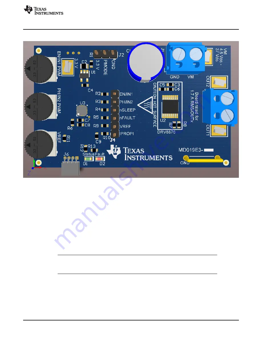
PCB (Top-Assembly View)
3
SLVUBG7C – August 2018 – Revised December 2019
Copyright © 2018–2019, Texas Instruments Incorporated
DRV8876/74 Evaluation Module
1
PCB (Top-Assembly View)
Figure 1. PCB (Top 3-D View)
2
Introduction
The DRV8876x/74xEVM is a complete solution for evaluating the DRV8876/74x H-bridge motor drivers. It
includes an MSP430™ microcontroller that is preprogrammed to take input from two dedicated analog
potentiometers for PWM speed control of one or two brushed DC motors. The jumper on the PMODE pin
allows the user to select from the input modes of PH/EN (GND), PWM (3.3 V), and independent half-
bridge control (Hi-Z). Power can be provided externally up to 37 V through the power header. To expand
beyond the included firmware capability, the MSP430 MCU can be reprogrammed through the eZ-FET
emulation circuit found in newer MSP430 Launchpads. We recommend the
. Note that a four pin angled male header is required and must be soldered to J21 of this
Launchpad from V+ pin to GND pin. We recommend a pin header with pin dimensions like 850-10-050-20-
001000. The U1 MCU must be removed from the Launchpad.
NOTE:
To test the DRV8876N functionality (no current sensing), replace R7 with a 0-Ohm resistor
and set VREF to a voltage greater than 1 V. This will configure the DRV8876 to the same
operation as the DRV8876N.
3
Power Connectors
The DRV8876/74xEVM uses a single header for power entry to the EVM board. Only a single power
supply rail is necessary since an onboard 3.3-V regulator provides power to the MSP430. The minimum
recommended VM voltage for the EVM is 4.5 V and the maximum is 37 V. For complete voltage range
information of the driver itself, refer to the device.