


Quick Start GUI
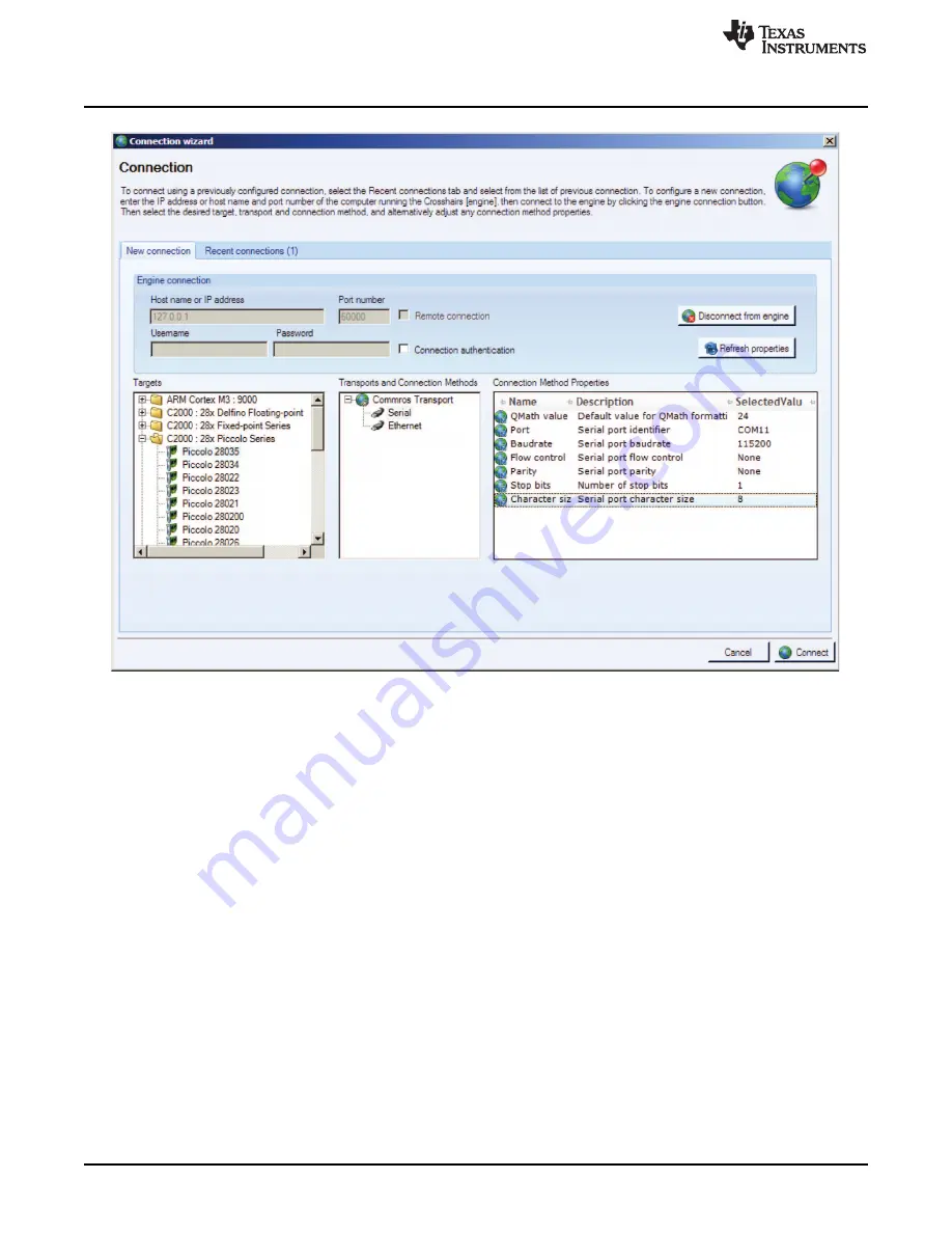
Figure 5. GUI Setup Connection
4.3.4
Image Correction
If an incorrect image is flashed on the controller, the connection fails. In this case, TI recommends re-
flashing the controller with the correct image.
4.3.5
Common Controls and Board Status Indicators
Common controls and board status indicators are located at the bottom of the screen and include:
•
Enable motor check box: The enable motor check box starts or stops the motor from running.
•
Control mode drop-down box: Allows the selection of four different control modes.
–
Duty cycle: The motor is commutated using the sensor-less algorithm, but is driven in an open-loop
duty cycle mode.
–
Current: The motor is commutated using the sensor-less algorithm, and the current (torque) is
regulated using a PI controller. (Note: An unloaded motor rapidly accelerates to a very high speed
in this mode.)
–
Velocity: The motor is commutated using the sensor-less algorithm, and the motor speed is
regulated using a PI controller. The output of the speed controller is a PWM duty cycle.
–
Cascade: The motor is commutated using the sensor-less algorithm, and the motor speed is
regulated using a PI controller. The output of the speed controller is a motor current command,
which is regulated by a lower level current PI controller.
•
Fault status: The on-screen LED turns red whenever there is a fault signaled by the DRV8303. To
reset this fault, ensure enable motor check box is unchecked and push the reset fault button
6
DRV8303EVM User Guide
SLVU983A – September 2013 – Revised October 2013
Copyright © 2013, Texas Instruments Incorporated