6 GUI Operations DRV8962
1. If not done so already turn off the power supply and connect your motors to the EVM in the desired
configuration. Both high side and low side load driving is possible and is open to the user to configure. Use
Jumpers J13 and J14 to connect the motors to the half bridges and J23 for VM and GND
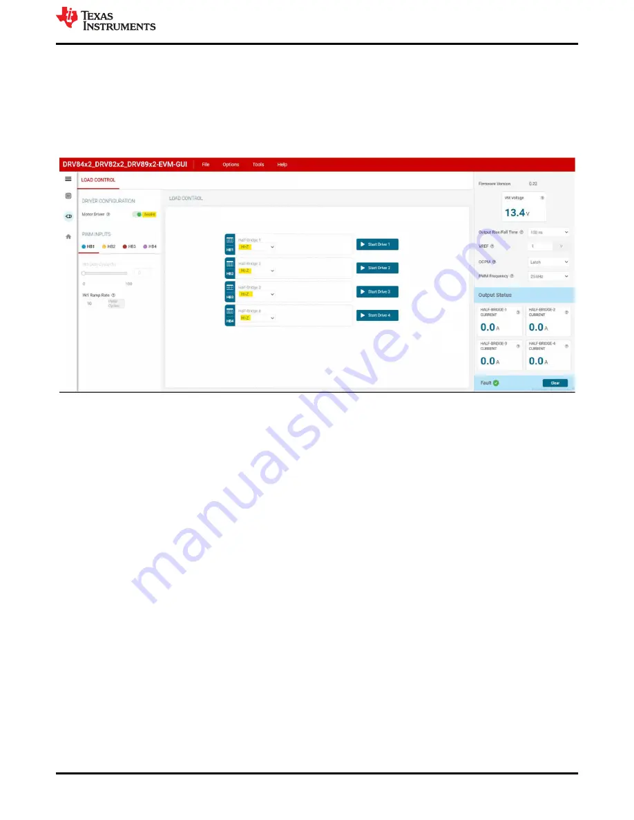
2. Go to the “LOAD CONTROL” tab in the “Driver Control” page. The VM Voltage widget will read out the input
voltage to J12. Set the “Motor Driver” to “Awake”. Using the drop-down menu displaying “Hi-Z” choose “Low
Side Load” for HB1, HB2, HB3 and HB4.
Figure 6-1. DRV8962 GUI
3. Press all the four “Start Drive 1,2,3 and 4” buttons. The HB1, HB2, HB3 and HB4 PWM INPUTS sliders
will turn active now. First set IN1 Duty Cycle to 50%. Motor-1 will start spinning and the motor current will
be displayed in the HALF-BRIDGE-1 display window. Next set IN2 Duty Cycle to 100% from the HB2 tab.
Motor-1 will slow down to zero speed and reverse direction. Now the motor current will be displayed in the
HALF-BRIDGE-2 display window. Repeat these steps for HB3 with 50% duty cycle and HB4 with 100% duty
cycle. This will spin Motor-2 and the currents will be displayed in HALF-BRIDGE-3 and HALF-BRIDGE-4
display windows similar to Motor-1. Switch the “Motor Driver” widget to “Asleep”. The motors will spin down
to a stop.
4. The section on the right will allow you to monitor the Output Status of each half bridge, clear faults, set the
PWM frequency, set the OCPM mode, output rise/fall time, and VREF for current regulation. Make sure to
only make this changes when the outputs are disabled. Changes might not be reflected if changed mid drive.
GUI Operations DRV8962
SLOU558 – AUGUST 2022
DRV84x2_DRV82x2_DRV89x2-EVM User's Guide
27
Copyright © 2022 Texas Instruments Incorporated


