


www.ti.com
4.6
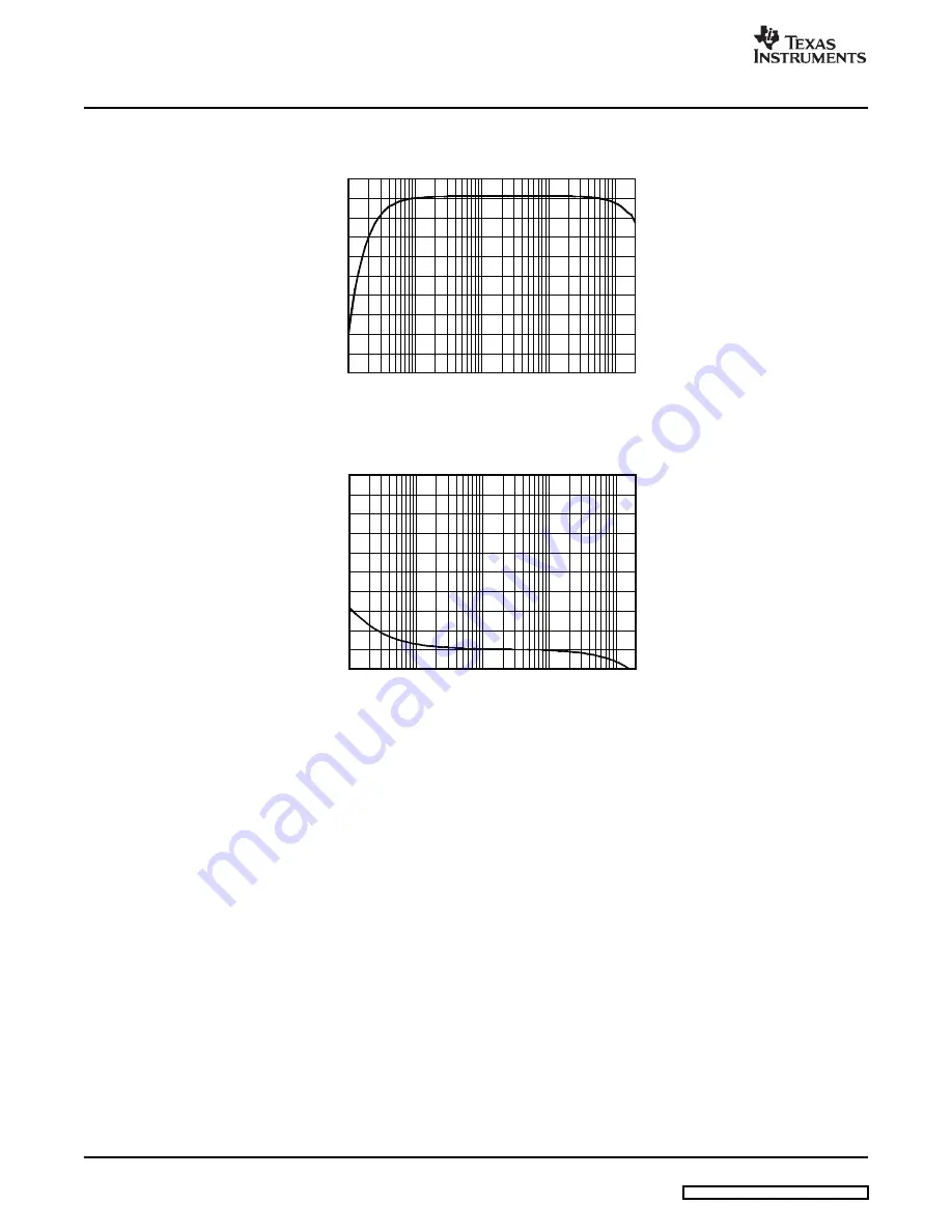
Frequency Response
4.0
3.6
3.2
2.8
2.4
2.0
1.6
1.2
0.8
0.4
0
Amplitude(dBrA)
0
Frequency (Hz)
100k
100k
1k
10k
200k
0
-
20
-
40
-
60
-
80
-
100
-
120
-
140
-
160
-
180
-
200
Phase(
)
°
0
Frequency (Hz)
100k
100k
1k
10k
200k
4.7
Pop/Click (Enable)
DRV600EVM Performance
Measurement bandwidth filter is set to 500kHz.
Figure 12. Frequency Response
Figure 13. Phase Response
The low frequency cutoff of 10Hz (–3dB) is determined by the input ac-coupling capacitor together with the
input impedance of the DRV600.
A 1
μ
F capacitor is used on the DRV600EVM. The input impedance of the DRV600 is 15k
Ω
. This
impedance gives a –3dB cutoff of 10Hz. This result corresponds with the frequency response
measurements above.
An RC filter is placed at the DRV600 to filter high-frequency noise. A 220
Ω
resistor and a 1nF NPO
capacitor is used. This configuration gives a –3dB frequency of 720kHz.
No input signal is applied. The measurement results are presented both in a time domain and in a
frequency domain. The resistor load is 600
Ω
in both examples.
The power supply is applied, and then the shutdown signal is released. The shutdown signal is used to
trigger the measuring system.
10
DRV600EVM User's Guide
SLOU205 – July 2007