Texas Instruments CPG004DRV88 EVM Series Скачать руководство пользователя страница 5

www.ti.com

Installing Drivers And Software

2

Installing Drivers And Software

2.1

Installing the FTDI USB Driver

Instructions on how to install the FTDI USB driver on a Windows based computer are detailed in the
“USB_Drivers_Install_Readme.pdf” file supplied with the CD inside the USB_Driver folder.

2.2

Installing the CPG004_DRV88xx Evaluation Board Windows Application Software

Copy the contents of the “WindowsApplication” folder provided within the CD, into your hard disk.

2.3

Running the Windows Application Software

To run the application, double click the CPG004_DRV88xxEVM_R0p2.exe application icon found on the
same folder the application was extracted into.

3

The Windows Application

The CPG004_DRV88xxEVM Windows application is the software counterpart for the CPG004_DRV88xx
EVM. It allows the PC computer to connect to the MSP430F1612 microcontroller though an USB interface
chip. Once connection is established and commands are sent, microcontroller takes care of configuring
control signals and administering certain levels of automation, such as microstepping generation for
(DRV8812/13), STEP and DIR control (for DRV8824/25) or PWM output (for DRV8812/13/14/41/43).

The graphical user interface (GUI) has been designed to allow for all of the DRV88xx device’s functionality
to be tested without having to intervene with the hardware, except for the proper configuration of jumpers,
when needed.

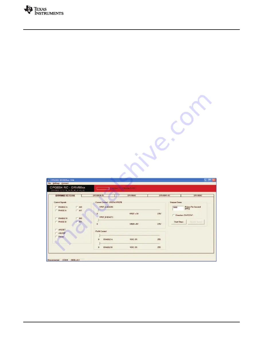
The following pictures show the CPG004_DRV88xxEVM_R1p1.exe main screen. The application is
divided into three tabs: one for each one of the three available device flavors. The menu contains items to
configure and enable/disable the serial port.

Figure 4. DRV8802-12-13-14 Tab

The DRV8802-12-13-14 tab contains all the control signals needed to control motor enablement (ENABLE
A, ENABLE B), direction of rotation (PHASE A, PHASE B) and current control (AIx and BIx). Access to
both DAC generating VREF analog voltages is achieved by moving sliders. Another set of sliders allow the
control of PWM duty cycle on ENABLE x pins. This is intended for motion control.

A simple stepper demo allows hooking a bipolar stepper to the DRV8812 EVM and have its speed and
direction controlled by an algorithm which modulates the VREF current in a high resolution microstepping
style. This function is achieved by using both MSP430 DAC outputs and is only available if respective
jumpers are set for dual DAC connection (as default).

5

SLVU361B – April 2010 – Revised October 2013

CPG004_DRV88xx Evaluation Modules

Submit Documentation Feedback

Copyright © 2010–2013, Texas Instruments Incorporated

Содержание CPG004DRV88 EVM Series

Страница 1: ...indows Application Software 5 3 The Windows Application 5 3 1 The Menu 7 3 2 DRV88xx GPIO Control Signals 7 3 3 Updating DAC Output for Current Control VREFA and VREFB 8 3 4 DC Motor Speed Control PWM...

Страница 2: ...e monitoring of the input power rail User must apply VM according to datasheet recommended parameters NOTE VDD for logic and microcontroller is derived from USB interface 1 2 Test Stakes Every pin on...

Страница 3: ...ion JP2 2 3 to select the respective variable resistance potentiometer This jumper should not be left open as lack of reference voltage on the device will minimize current sourcing into the respective...

Страница 4: ...RV8802 12 13 14 JP1 3 4 DRV8824 25 JP1 5 6 DRV8841 43 JP1 3 4 1 3 3 DECAY Select Jumper JP3 Figure 3 DECAY Select Jumper Configuration 1 4 Motor Outputs There are two ways of connecting the different...

Страница 5: ...hical user interface GUI has been designed to allow for all of the DRV88xx device s functionality to be tested without having to intervene with the hardware except for the proper configuration of jump...

Страница 6: ...of microstepping Figure 6 DRV8841 43 Tab The DRV8841 43 tab is very similar to the DRV8802 12 13 14 tab except correct naming conventions have been followed to showcase the AINx pins instead of PHASE...

Страница 7: ...connect Press Disconnect to disable the serial communications 3 1 0 0 should return on the text box as an acknowledge The text box also changes from red to green 4 The application is ready for use 3 2...

Страница 8: ...ut voltage DAC_VALUE is a number from 0 to 4095 Moving the sliders will update the VREF xV caption below each respective slider with the result of the previous equation giving the user an idea of what...

Страница 9: ...f operation the motor is ready to be turned The DRV88xx EVM allows for the possibility of coordinating step rates such that accelerating and decelerating profiles are achieved Both acceleration and de...

Страница 10: ...ion When the motor is stepping the Update Speed button becomes enabled Speed can be updated by modifying the PPS text box and then pressing the Update Speed button The Speed Button is disabled every t...

Страница 11: ...the PPS text box The user must then provide number of steps per resolution the motor has been manufactured to achieve For example a 1 8 degrees stepper motor would have 200 steps per revolution and so...

Страница 12: ...i com 4 Schematics See the following pages for schematics 12 CPG004_DRV88xx Evaluation Modules SLVU361B April 2010 Revised October 2013 Submit Documentation Feedback Copyright 2010 2013 Texas Instrume...

Страница 13: ...F C5 1 2 3 4 5 6 JP1 BVREF_SEL AVREF VDD 3 3K R1 nFAULT VDD 3 3K R4 BI1 nHM BI1 10K R8 GND 2 2 3 3 1 1 JP3 DECAY_SEL VDD DECAY GDECAY 0 1uF C12 GND D1 VM 1 2 J1 VM 1 2 3 4 J3 V3P3OUT V3P3OUT 330 R20 D...

Страница 14: ...1 34 P4 2 TB2 38 P4 5 TB5 41 P5 2 SOMI1 46 P5 5 SMCLK 49 XT2OUT 52 TDI TCLK 55 P6 0 A0 59 AVSS 62 P4 6 TB6 42 U2 MSP430F1612 GND GND GND 10uF C15 10uF C17 0 1uF C16 33pF C19 33pF C20 1 2 3 4 5 6 7 8 9...

Страница 15: ...PHA DIR AIN2 1 TP29 GND GND 1 TP25 VM 1 TP26 VDD VM VDD 1 TP28 GND GND 1 TP33 GND GND 1 TP32 GND GND 1 TP30 GND GND 1 TP31 GND GND 1 TP27 VM VM A TexasInstruments 3 of 3 CPG004 Sheet B InputVoltageVC...

Страница 16: ...Page Changed figure 5 and supporting text below image 6 NOTE Page numbers for previous revisions may differ from page numbers in the current version 16 Revision History SLVU361B April 2010 Revised Oc...

Страница 17: ...ncy energy and has not been tested for compliance with the limits of computing devices pursuant to part 15 of FCC or ICES 003 rules which are designed to provide reasonable protection against radio fr...

Страница 18: ...na type and its gain should be so chosen that the equivalent isotropically radiated power e i r p is not more than that necessary for successful communication This radio transmitter has been approved...

Страница 19: ...roduct only after you obtained the license of Test Radio Station as provided in Radio Law of Japan with respect to this product or 3 Use of this product only after you obtained the Technical Regulatio...

Страница 20: ...erations per the user guidelines Exceeding the specified EVM ratings including but not limited to input and output voltage current power and environmental ranges may cause property damage personal inj...

Страница 21: ...sponsible for compliance with all legal regulatory and safety related requirements concerning its products and any use of TI components in its applications notwithstanding any applications related inf...

Отзывы: