


SWRU139
CC2520 Development Kit Quick Start Guide
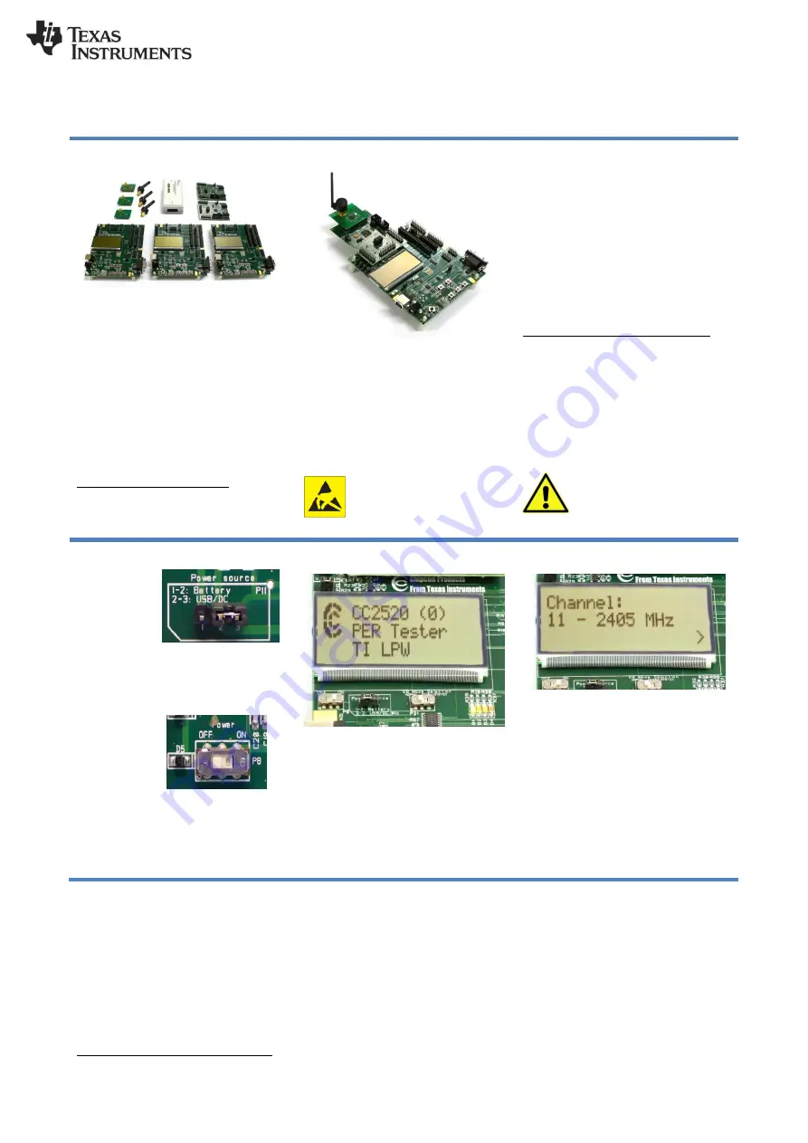
1. Kit Contents
3 x SmartRF05 Evaluation Boards
2 x MSP430F2618 Sandwich Boards
3 x CC2520 Evaluation Modules
3 x Pulse W1010 antennas
1 x MSP430 Debugger
Cables & Documentation
The CC2520EM in this kit is FCC/IC
certified and complies with ETSI/R&TTE
over temperature from 0 to +35°C.
The antenna, W1010 from Pulse, is a ¼
wave dipole antenna with 2 dBi gain.
FCC/IC Regulatory Compliance
FCC Part 15 Class A Compliant
IC ICES-003 Class A Compliant
2. Assemble the Boards
Insert the MSP430 sandwich boards
(called CCMSP-EM430F2618) into the
SmartRF05EBs. Connect antennas to both
of the CC2520EM. Make sure the
antennas are firmly attached to the SMA
connector. If not, RF performance may be
reduced. Insert the CC2520EM into the
MSP430 board. Do not use excessive
force when assembling the boards.
Caution!
The kit contains ESD sensitive
components. Handle with care to prevent
permanent damage. To minimize risk of
injury, avoid touching components during
operation if symbolized as hot.
3. Power Options
There are several ways of applying power
to the SmartRF05EB;
USB (5V through USB plug)
External Power Supply
(requirements below)
2 x 1.5V AA Non-Rechargeable
Alkaline Batteries
Voltage regulators on the SmartRF05EB
will set the on-board voltage to 3.3V.
External Power Supply
1
Requirements:
Nom Voltage: 4 to 20 VDC
Max Current: 1500 mA
Efficiency Level V
Warning!
To minimize risk of personal
injury or property damage, never use
rechargeable batteries to power the board.
There should only be one
active power source connected
to the board at any time.
4. Select Power Source
Locate
the
power source
header
P11
just above the
LCD on the
SmartRF05EB
Connect pins 1 and 2 if you are using
batteries to power the board. Connect pins
2 and 3 if you are using USB or external
power supply.
Once you have
set P11, find
switch P8 just
next to the DC
jack
on
the
SmartRF05EB.
To power on
the board, flip the switch form “OFF” to
“ON”.
Do not leave the EVM powered when
unattended.
5. Packet Error Rate Tester
When power is turned on, the Packet Error
Rate
Test
program,
which
is
preprogrammed on the MSP430, will start
running.
The LCD should display the screen as
shown in the picture above. Press Button 1
to enter the menu.
6. Set Channel
Select a channel between 11 and 26
(2405-2480 MHz). The channel is selected
by pushing the joystick to the right or left.
Confirm the selection by pressing Button 1.
1
When using an external power supply, make sure it meets the listed requirements in addition to complying with applicable regional
product regulatory and safety certification requirements such as UL, CSA, VDE, CCC, and PSE.