Texas Instruments BQ79600-Q1 Скачать руководство пользователя страница 12

BQ79600EVM Quick Start Guide

www.ti.com

12

SLUUC57A – October 2019 – Revised June 2020

Submit Documentation Feedback

Copyright © 2019–2020, Texas Instruments Incorporated

BQ79600-Q1 Evaluation Module

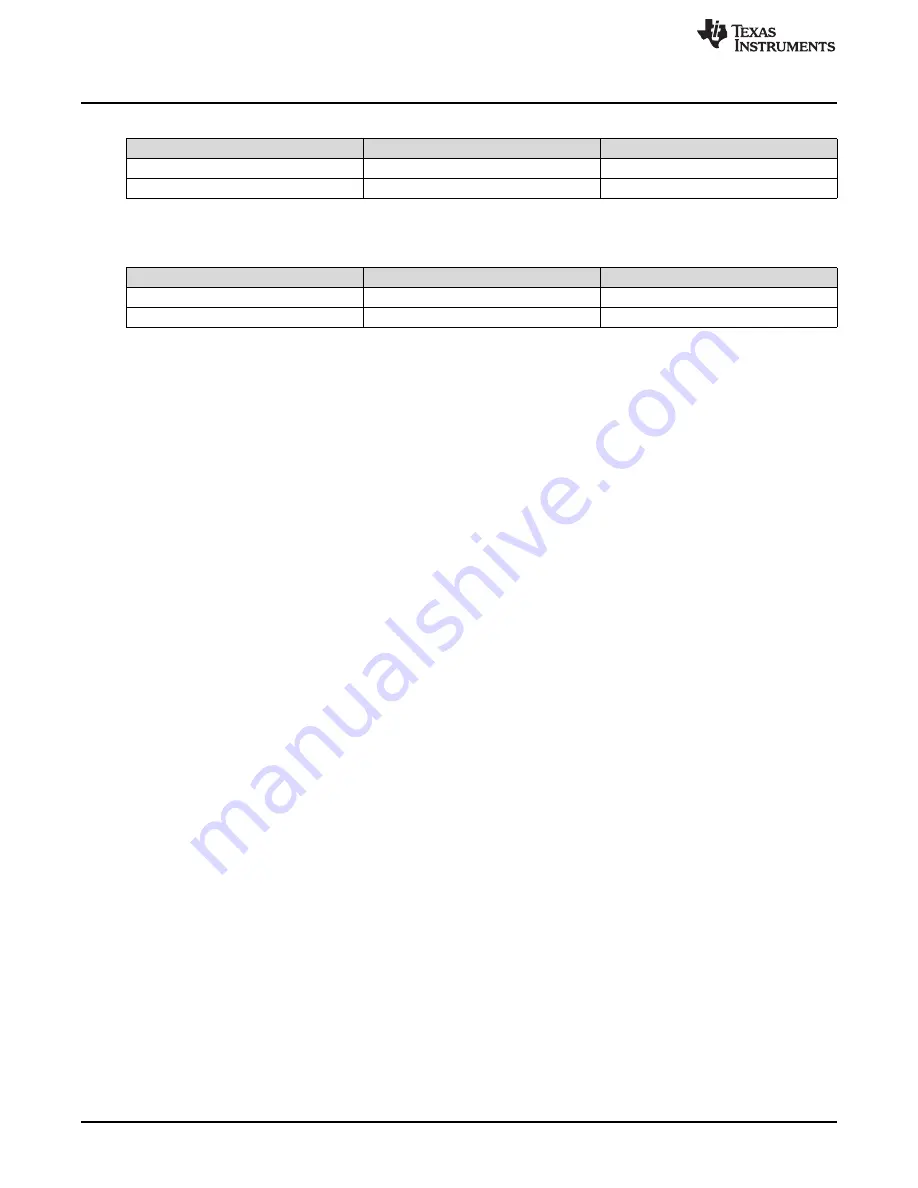
Table 13. Connections Between BQ79600EVM High Side and BQ79616EVM Low Side

Connection Name

BQ79600EVM High Side

BQ79616EVM Low Side

COMH_N to COML_N

J15 pin 4

J10 pin 1

COMH_P to COML_P

J15 pin 3

J10 pin 2

Table 14. Connections Between BQ79616EVM High Side and BQ79600EVM Low Side (for ring

architecture only)

Connection Name

BQ79600EVM Low Side

BQ79616EVM High Side

COML_N to COMH_N

J14 pin 1

J11 pin 4

COML_P to COMH_P

J14 pin 2

J11 pin 3

4.5

Software

The software provides a command API and drivers that are capable of implementing the examples
provided in the

BQ79600-Q1 Software Design Reference

document.

The example code only provides a control interface to the BQ79600-Q1 and BQ79616-Q1 and does not
provide any other communications interface to the outside world. The customer is expected to develop
their own communication implementation. Two examples are available using TMS570 micocontroller:

Example code using UART communication protocol between the microcontroller and BQ79600-Q1
device

Example code using SPI communication protocol between the microcontroller and BQ79600-Q1 device

Importing a project into

Code Composer Studio

™:

1. Launch the provided file:

BQ79600-Q1 UART Example Code 1.0 Installer.exe

or

BQ79600-Q1 SPI

Example Code 1.0 Installer.exe

and extract files to the default path provided (C:\ti\bq79600-Q1 UART

Example Code 1.0 or C:\ti\bq79600-Q1 SPI Example Code 1.0)

2. Launch

Code Composer Studio

(CCS):

Start

Programs

Texas Instruments

Code Composer Studio v8

Code Composer

Studio v8

3. When it launches, CCS requests a workspace is selected, choose “C:\myWorkspace”. Once CCS

loads, go to:

Project

Import CSS Projects...

Select search-directory

4. In Select search-directory, browse to the folder:

C:\ti\bq79600-Q1 UART Example Code 1.0 or C:\ti\bq79600-Q1 SPI Example Code 1.0

5. In

Discovered projects:

, check

BQ79600-Q1 UART example code

or

BQ79600-Q1 SPI example code

4.6

GUI

For initial evaluation, it may be more beneficial to use the graphical user's interface (GUI), which provides
a "point and click" interface to become familiar with the BQ79600. During the initial sampling phase,
contact your local TI FAE to get the latest GUI version.

To get started with the GUI, please refer to the

BQAutoEval GUI User's Guide

.

4.6.1

GUI UART/SPI Connection

The physical setup for the GUI is the same as for the microcontroller, but will instead use an USB2ANY
interface and 10-pin cable for the UART/SPI connections on J4. The USB2ANY has a USB Mini-B
connector on the right side. Plug the provided USB cable (or any USB cable with a Mini-B connector) into
the USB2ANY. Plug the other end of the cable (USB ‘A’) into the computer. Then connect the 10-pin
connector cable to J4 of the USB2ANY (middle most connector) and the key side must be facing upwards
when connecting to the EVM header J4. Refer to

Figure 6

and this is explained in more detail in the

USB2ANY Interface Adapter User's Guide

and the

BQAutoEval GUI User's Guide

.

Содержание BQ79600-Q1

Страница 1: ...2 Theory of Operation 3 3 Connectors 4 4 BQ79600EVM Quick Start Guide 10 5 Physical Dimensions 13 6 Schematics Assembly Layout and Bill of Materials BOM 13 List of Figures 1 System Block Diagram 3 2 K...

Страница 2: ...is equipped with an UART SPI interface to enable a host device to communicate to the BQ79600 Q1 device and an isolated differential daisy chain interface to enable communication to a stack of battery...

Страница 3: ...k frequency 2 Mbps to 6 Mbps UART baud rate 1 Mbps 2 Theory of Operation Figure 1 shows the system stack diagram Figure 1 System Block Diagram The typical BMS system consists of a Battery Management U...

Страница 4: ...will be stopped automatically 7 The host can then decide to repeat the process back to step 4 or return later When using the BQ79616 Q1 in a ring architecture the host can enable the sniffer detector...

Страница 5: ...ND for UART 2 3 Yes 2 3 J12 1 2 2 3 SCLK pullup to VIO 1 2 or pulldown to GND for SPI UART 2 3 Yes 2 3 J13 1 2 NFAULT pullup to VIO Yes 3 1 2 Power Supply The power supply connection is made from eith...

Страница 6: ...communication 11 COMLN AC coupled bi directional I O pin for daisy chain VIF communication 12 COMHP AC coupled bi directional I O pin for daisy chain VIF communication 13 COMHN AC coupled bi direction...

Страница 7: ...ng the GUI or to a host controller through a TTL 232R 5V FTTI cable Only UART is supported Figure 4 Molex 0022124062 reference image only Table 6 Connector Information Designator Manufacturer Part Num...

Страница 8: ...570LS12x LaunchPad Table 8 Pin Description J7 Pin Name 1 MCU 3 3 V 2 TMS570LS12x LaunchPad 5 V 3 NC 4 GND 5 MCU RX MISO_TX of BQ79600 Q1 6 NC 7 MCU TX MOSI_RX of BQ79600 Q1 8 NC 9 NC 10 NC 11 NC 12 NC...

Страница 9: ...ble on each board These provide high side J15 and low side J14 communications between stacked EVM devices Table 10 Connector Information Designator Manufacturer Part Number Mating Connector J14 J15 Mo...

Страница 10: ...eStore https estore ti com or from your local TI sales representative For more details and information related to the LaunchPad modules see the specific module user s guide 4 2 Power Connections The B...

Страница 11: ...and JP6 are placed and JP1 is removed The EVM and the MCU are connected using the female connectors J7 and J9 on the bottom side of the BQ79600EVM and the male connectors J2 J3 J4 and J5 on the top si...

Страница 12: ...exe and extract files to the default path provided C ti bq79600 Q1 UART Example Code 1 0 or C ti bq79600 Q1 SPI Example Code 1 0 2 Launch Code Composer Studio CCS Start Programs Texas Instruments Cod...

Страница 13: ...mensions Board dimensions 2 300 in 5 130 in Board height Top Tallest component shunts is 0 35 in 8 8 mm above PCB Bottom Tallest component transformers is 0 41 in 10 5 mm above PCB 5 2 Board Mounting...

Страница 14: ...www ti com 14 SLUUC57A October 2019 Revised June 2020 Submit Documentation Feedback Copyright 2019 2020 Texas Instruments Incorporated BQ79600 Q1 Evaluation Module 6 1 Schematics Figure 9 BQ79600EVM S...

Страница 15: ...bly Layout and Bill of Materials BOM 15 SLUUC57A October 2019 Revised June 2020 Submit Documentation Feedback Copyright 2019 2020 Texas Instruments Incorporated BQ79600 Q1 Evaluation Module Figure 11...

Страница 16: ...OM www ti com 16 SLUUC57A October 2019 Revised June 2020 Submit Documentation Feedback Copyright 2019 2020 Texas Instruments Incorporated BQ79600 Q1 Evaluation Module 6 2 Assembly Figure 12 BQ79600EVM...

Страница 17: ...f Materials BOM 17 SLUUC57A October 2019 Revised June 2020 Submit Documentation Feedback Copyright 2019 2020 Texas Instruments Incorporated BQ79600 Q1 Evaluation Module 6 3 Layout Figure 14 BQ79600EVM...

Страница 18: ...aterials BOM www ti com 18 SLUUC57A October 2019 Revised June 2020 Submit Documentation Feedback Copyright 2019 2020 Texas Instruments Incorporated BQ79600 Q1 Evaluation Module Figure 16 BQ79600EVM To...

Страница 19: ...19 SLUUC57A October 2019 Revised June 2020 Submit Documentation Feedback Copyright 2019 2020 Texas Instruments Incorporated BQ79600 Q1 Evaluation Module Figure 18 BQ79600EVM Internal Signal Layer 1 G...

Страница 20: ...rials BOM www ti com 20 SLUUC57A October 2019 Revised June 2020 Submit Documentation Feedback Copyright 2019 2020 Texas Instruments Incorporated BQ79600 Q1 Evaluation Module Figure 20 BQ79600EVM Botto...

Страница 21: ...mbly Layout and Bill of Materials BOM 21 SLUUC57A October 2019 Revised June 2020 Submit Documentation Feedback Copyright 2019 2020 Texas Instruments Incorporated BQ79600 Q1 Evaluation Module Figure 22...

Страница 22: ...s panhead Screw NY PMS 440 0025 PH B F Fastener Supply H4 H5 H6 3 Standoff Hex 0 5 L 4 40 Nylon Standoff 1902C Keystone H7 H8 2 Rectangular Housing Connector 4 Pos 2 54mm 50 57 9404 Molex J1 J3 J6 J10...

Страница 23: ...SH9 9 Shunt 100mil Gold plated Black Shunt 2 pos 100 mil 881545 2 TE Connectivity T1 T2 2 BMS TRANSFORMER SMT_TRANSFORME R_8MM89_10MM09 HMU1228NL Pulse TP1 TP2 TP3 TP4 TP5 TP6 TP7 TP10 TP11 TP12 TP13...

Страница 24: ...ack Copyright 2019 2020 Texas Instruments Incorporated Revision History Revision History NOTE Page numbers for previous revisions may differ from page numbers in the current version Changes from Origi...

Страница 25: ...e resources are subject to change without notice TI grants you permission to use these resources only for development of an application that uses the TI products described in the resource Other reprod...

Отзывы: