bq51013AEVM-765 Assembly Drawings and Layout
www.ti.com
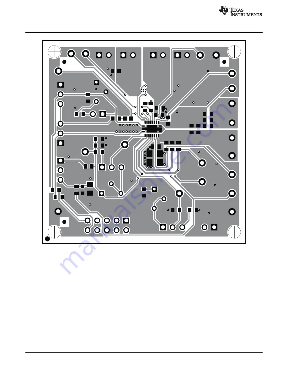
Figure 12. Top Copper Layer
14
bq51013AEVM-765 Evaluation Module
SLUU911 – June 2012
Submit Documentation Feedback
Copyright © 2012, Texas Instruments Incorporated
Страница 1: ...Equipment 6 6 2 Equipment Setup 7 6 3 Load Step 8 6 4 Load Dump 9 6 5 V Adapter Input 9 6 6 Start Up 10 6 7 Disable Shutdown 10 6 8 System Efficiency 11 6 9 Dynamic Rectifier Control Dynamic Efficienc...
Страница 2: ...EVM 765 Electrical Performance Specifications Table 1 provides a summary of the bq51013AEVM 765 performance specifications All specifications are given for an ambient temperature of 25 C Table 1 bq510...
Страница 3: ...able signals that controls the Adapter and Wireless power transfer Low on EN2 enables the adapter power transfer also High disables Comm IILIM Default Shorting jumper setting is Low 4 2 3 JP3 TS Enabl...
Страница 4: ...ve connects to the integrated circuit IC 4 3 9 TP9 Boot 2 Boot Capacitor This bootstrap capacitor 2 drive connects to the IC 4 3 10 TP10 CHG Charge This output signal indicates that the output current...
Страница 5: ...s 5 Schematic and Bill of Materials NOTE For Reference Only See Table 2 for Specific Values Figure 1 HPA765AEVM Schematic 5 SLUU911 June 2012 bq51013AEVM 765 Evaluation Module Submit Documentation Fee...
Страница 6: ...1 4 in Cermet 12 Turn 0 25x0 17 3266W 1 204LF Bourns Top Adjust 1 R4 110 Resistor Chip 1 16W 1 0603 Std Std 0 R6 R12 Open Resistor Metal Film 1 4 watt 1 1206 CRCW120624R0FKEA Vishay 1 R7 1 50K Resist...
Страница 7: ...ichannel oscilloscope with appropriate probes is used to observe the RECT voltage at TP12 and other signals 6 1 6 Recommended Wire Gauge For proper operation 22 AWG wire is recommended when connecting...
Страница 8: ...s must be Kelvin connected at the pin to the point of interest The output load is recommended to be a variable power resistor or electronic load 6 3 Load Step The procedure for load step is as follows...
Страница 9: ...oltage as shown in the following illustration Figure 4 Load Dump 500 mA to 0 mA 6 5 V Adapter Input The procedure for external adapter wired adapter testing is as follows Set up the test bench as desc...
Страница 10: ...6 Start Up 6 7 Disable Shutdown The jumper JP1 EN1 sends an End Power Transfer to Transmitter Shutdown With unit operating normally move jumper JP1 from Low to High position LED D1 turn OFF output vol...
Страница 11: ...total output currents This is demonstrated with the higher value for R I lim resulting in lower total output current See data sheet for additional information regarding Dynamic Efficiency Scaling Figu...
Страница 12: ...LIM 10 mA AD AD_EN TS CTRL EN1 EN2 TERM FOD 1 mA CHG 10 mA It is also recommended to have the following capacitance on RECT and OUT RECT 10 F OUT 1 F It is always good practice to place high frequency...
Страница 13: ...ng a 2 layer 2 oz copper clad PCB 2 1 in 2 1 in area to provide the user easy viewing probing and evaluating of the bq51013A IC in a practical double sided application Moving components to both sides...
Страница 14: ...AEVM 765 Assembly Drawings and Layout www ti com Figure 12 Top Copper Layer 14 bq51013AEVM 765 Evaluation Module SLUU911 June 2012 Submit Documentation Feedback Copyright 2012 Texas Instruments Incorp...
Страница 15: ...om bq51013AEVM 765 Assembly Drawings and Layout Figure 13 Bottom Copper Layer 15 SLUU911 June 2012 bq51013AEVM 765 Evaluation Module Submit Documentation Feedback Copyright 2012 Texas Instruments Inco...
Страница 16: ...tion about the bqTESLA products visit the Wireless Power Solutions folder on the TI Web site at http www ti com ww en analog wireless_power_solutions 16 bq51013AEVM 765 Evaluation Module SLUU911 June...
Страница 17: ...ncy energy and has not been tested for compliance with the limits of computing devices pursuant to part 15 of FCC or ICES 003 rules which are designed to provide reasonable protection against radio fr...
Страница 18: ...na type and its gain should be so chosen that the equivalent isotropically radiated power e i r p is not more than that necessary for successful communication This radio transmitter has been approved...
Страница 19: ...roduct only after you obtained the license of Test Radio Station as provided in Radio Law of Japan with respect to this product or 3 Use of this product only after you obtained the Technical Regulatio...
Страница 20: ...property damage personal injury or death If there are questions concerning these ratings please contact a TI field representative prior to connecting interface electronics including input power and in...
Страница 21: ...or use in safety critical applications such as life support where a failure of the TI product would reasonably be expected to cause severe personal injury or death unless officers of the parties have...