www.ti.com
bq501210EVM-756 Assembly Drawings and Layout
23
SLVUAO6 – June 2016
Submit Documentation Feedback
Copyright © 2016, Texas Instruments Incorporated
bq501210 bqTESLA™ Wireless Power TX EVM
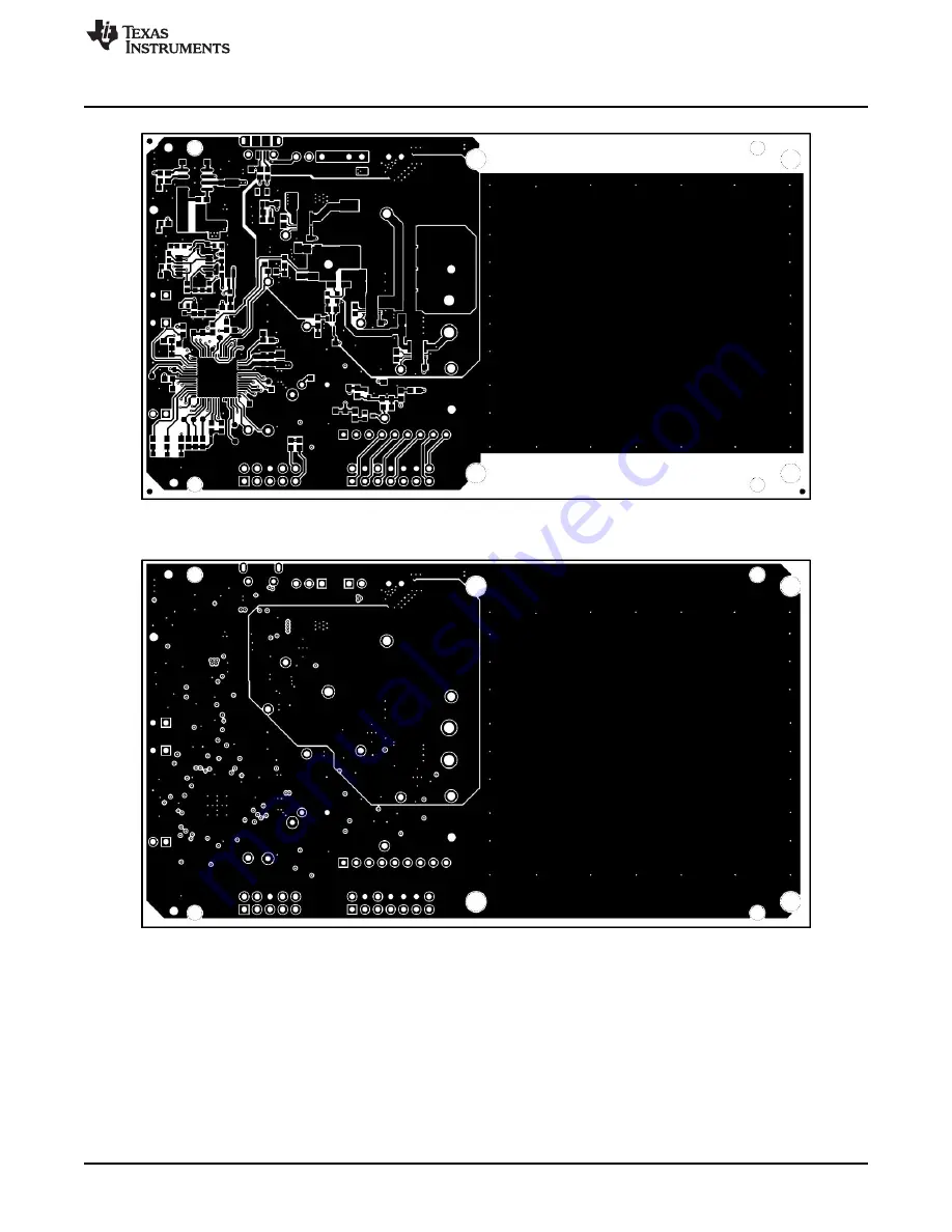
Figure 17. Top Layer
Figure 18. Inner Layer 1
Страница 1: ...with a WPC v1 2 15 W receiver Contents 1 Applications 2 2 bq501210EVM 756 Electrical Performance Specifications 2 3 Modifications 3 4 Connector and Test Point Descriptions 3 4 1 Input Output Connectio...
Страница 2: ...r to power transfer WPC v1 2 FOD WPC v1 1 FOD and WPC v1 0 Parasitic Metal Object Detection PMOD Transmitter coil mounting pad providing the correct receiver interface Compact power section design usi...
Страница 3: ...scribed in Section 4 1 1 through Section 4 1 9 4 1 1 J1 VIN Input power 12 V to 19 V return at J2 15 V to 19 V recommended for full 15 W delivery 4 1 2 J2 GND Return for input power input at J1 4 1 3...
Страница 4: ...test point TP 4 2 5 TP5 Low Noise Analog Ground Low noise ground TP 4 2 6 TP6 PEAK_DET Peak detect circuit input to PEAK_DET of bq501210 4 2 7 TP7 Demodulation Comm Output Primary communications chann...
Страница 5: ...voltage from rail buck converter that feeds H Bridge power section 4 2 19 TP19 PWM_RAIL Digital input to rail converter power section from bq501210 Signal is PWM used to control rail voltage 4 2 20 TP...
Страница 6: ...SE TP22 0 1 F C38 10 0k R45 RAIL SNOOZE JP3 RAIL FP_GAIN 76 8k R10 TCK PEAK_DET 1 RESERVED 2 V_IN 3 T_SENSE 4 I_SENSE 5 UNUSED 6 V33DIO 7 DGND 8 RESET 9 RESERVED 10 LED A 12 LED B 13 SNOOZE 14 CLK 15...
Страница 7: ...ED 36 RESERVED 37 RESERVED 38 RESERVED 39 RESERVED 40 RX_PROP 41 D HI 42 DGND 43 V33DIO 44 V33D 45 V33A 46 BPCAP 47 AGND2 48 AGND 49 COMM_A 50 COMM_A 51 COMM_B 52 COMM_B 53 V_RAIL 54 V_RAIL 55 COMM_C...
Страница 8: ...F C8 130k R2 3V3 TP9 1 4 5 2 6 3 U7 BQ500100DCK RAIL 10 0 R12 0 01 F C35 10 0k R3 1 00k R22 RAIL 10 0 R13 TP8 I_SENSE 0 1 F C41 Current Sense Copyright 2016 Texas Instruments Incorporated Schematic an...
Страница 9: ...9 4700pF C18 0 047 F C16 C11 3V3 0 1 F C45 200k R6 23 2k R14 TP7 COMM 10 0 R29 1 3 2 D10 30V 33pF C14 10 0k R5 COMM 10 0 R19 1 3 2 D3 30V TP6 PEAK_DET 10 0 R20 330pF C37 1 00Meg R18 Coil Control To VS...
Страница 10: ...TP12 TP17 2700pF C32 D2 Green NT1 Net Tie 3 16k R4 NT2 Net Tie J2 GND VGATE 1 GND OUT 3 IN 2 NC 4 NC 5 U6 TLV70450DBVT 511k R34 0 1 F C33 1 F C39 1 3 2 D11 30V 511k R36 PWR_UP 1 00Meg R21 4 7 F C40 Q1...
Страница 11: ...3V3 5 6 7 B V V 4 11 U8B 604 R53 1 00k R58 2 4 1 5 3 U9 SN74AHC1G08DRLR D9 Green 8 10 9 C V V 4 11 U8C 1 00k R59 14 12 13 D V V 4 11 U8D D5 Green 1 20k R55 12 1k R57 HVDCP EVM Only 0 1 F C47 1 F C48...
Страница 12: ...5 C40 3 4 7uF CAP CERM 4 7uF 10V 10 X5R 0603 0603 CGB3B1X5R1A475K055AC TDK C4 C18 C23 3 4700pF CAP CERM 4700pF 50V 10 X7R 0603 0603 GRM188R71H472KA01D Murata C6 C27 2 10uF CAP CERM 10uF 35V 10 X7R 121...
Страница 13: ...R42 4 475 RES 475 ohm 1 0 1W 0603 0603 CRCW0603475RFKEA Vishay Dale R16 1 100k RES 100k ohm 1 0 1W 0603 0603 CRCW0603100KFKEA Vishay Dale R18 R21 R41 3 1 00Meg RES 1 00Meg ohm 1 0 1W 0603 0603 CRCW06...
Страница 14: ...ser manual External Power Supply Requirements Nom Voltage 15 0 19 0 VDC Max Current 2 0 A Efficiency Level V External Power Supply Regulatory Compliance Certifications Recommend selection and use of a...
Страница 15: ...6 2 Equipment Setup Verify jumper positions JP1 Shorted JP2 Open JP3 Open JP4 19 V input selected With the power supply OFF connect the supply to the bq501210EVM 756 transmitter Connect the VIN positi...
Страница 16: ...ED D2 is flashing LEDs D6 D7 D8 D9 and D12 are OFF until the power transfer starts Apply the scope probe to the TX test point TP15 drive B Figure 9 shows TP15 and the input current during the ping sta...
Страница 17: ...power to the input power Connect voltage meters at the input and output of TX and RX see Figure 7 Average the input current the communication pulses modulate the input current distorting the reading F...
Страница 18: ...ver is present it powers up and replies then begins the power transfer Figure 11 is a scope capture of the bq501210EVM 756 beginning a power transfer with the 15 W RX Figure 11 Start Up The bq501210 d...
Страница 19: ...current is measured using sense resistor R28 and current sense amp U7 bq500100 Since these measurements are used to calculate the power lost through a foreign object both measurements must be accurate...
Страница 20: ...orated bq501210 bqTESLA Wireless Power TX EVM 6 2 2 9 Thermal Performance This section shows a thermal image of the bq501210EVM 756 A 1500 mA load is used at the 10 V 15 W receiver output Output power...
Страница 21: ...le for download from the EVM product folder bq501210EVM 756 A 4 layer PCB design is recommended to provide a good low noise ground plane for all circuits A 2 layer PCB presents a high risk of poor per...
Страница 22: ...ssembly Drawings and Layout www ti com 22 SLVUAO6 June 2016 Submit Documentation Feedback Copyright 2016 Texas Instruments Incorporated bq501210 bqTESLA Wireless Power TX EVM Figure 15 Assembly Top Fi...
Страница 23: ...0EVM 756 Assembly Drawings and Layout 23 SLVUAO6 June 2016 Submit Documentation Feedback Copyright 2016 Texas Instruments Incorporated bq501210 bqTESLA Wireless Power TX EVM Figure 17 Top Layer Figure...
Страница 24: ...e 19 Inner Layer 2 Figure 20 Bottom Layer 8 Reference For additional information about the bq50120 WPC v1 2 Wireless Power Transmitter with 15 W Power Delivery and its Evaluation module visit the prod...
Страница 25: ...ing the warranty period to the address designated by TI and that are determined by TI not to conform to such warranty If TI elects to repair or replace such EVM TI shall have a reasonable time to repa...
Страница 26: ...transmitter has been approved by Industry Canada to operate with the antenna types listed in the user guide with the maximum permissible gain and required antenna impedance for each antenna type indic...
Страница 27: ...ified allowable ranges some circuit components may have elevated case temperatures These components include but are not limited to linear regulators switching transistors pass transistors current sens...
Страница 28: ...REMOVAL OR REINSTALLATION ANCILLARY COSTS TO THE PROCUREMENT OF SUBSTITUTE GOODS OR SERVICES RETESTING OUTSIDE COMPUTER TIME LABOR COSTS LOSS OF GOODWILL LOSS OF PROFITS LOSS OF SAVINGS LOSS OF USE L...
Страница 29: ...sponsible for compliance with all legal regulatory and safety related requirements concerning its products and any use of TI components in its applications notwithstanding any applications related inf...