GUI Application
21
SLVUB00B – February 2017 – Revised March 2018
Copyright © 2017–2018, Texas Instruments Incorporated
BOOSTXL-DRV8320x EVM User’s Guide
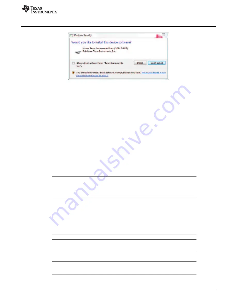
Figure 32. TI MSP430 USB Installer
If the automatic driver installation fails for some reason, or if the
Don’t Install
button was clicked, install the
drivers manually. First find the driver .inf file (msp430_ti_signed.inf) in the following folder: C:\Program
Files (x86)\Texas Instruments\BOOSTXL-DRV832X\TI MSP430 USB Driver. Right click on the .inf file and
select the
Install
option. Follow the installation instructions to successfully install the driver.
If any issues occur during the driver installation steps or to learn more about the process, download and
extract the
MSP430 USB Developers Package
from
www.ti.com/tool/msp430usbdevpack
and refer to
sections 2.5.2 for Windows 7 and 2.5.3 for Windows 8 in the document
Examples_Guide_MSP430_USB.pdf
based on the appropriate Windows. This document can be found
under the
MSP430USBDevelopersPackage_5_10_00_17\MSP430_USB_Software\Documentation
directory of the extracted
MSP430 USB Developers Package
.
4.2
Hardware Setup
The hardware required to run the motor control is an MSP430F5529 LaunchPad development kit, the
BOOSTXL-DRV8320x BoosterPack plug-in module, a Micro-USB cable, and a power supply with a DC
output from 8 to 54 V. Follow these steps to start up the BoosterPack plug-in module:
Step 1.
Dock the BOOSTXL-DRV8320x BoosterPack plug-in module to the MSP430F5529
LaunchPad development kit through the two 40-pin headers J1 and J2.
NOTE:
Observe the correct polarity of the 40-pin LaunchPad headers. The MSP430F5529
LaunchPad header J1 should be connected to the DRV8320x BoosterPack header J1 and
MSP430F5529 LaunchPad header J2 should be connected to BOOSTXL-DRV8320x
BoosterPack header J2.
Step 2.
Connect the three phases from the brushless DC motor to the J4 connector on the
BOOSTXL-DRV8320x BoosterPack plug-in module. Phase A, B, and C are labeled in white
silkscreen on the PCB top layer.
NOTE:
If using the sensored firmware on the MSP430F5529 LaunchPad development kit, connect a
brushless DC motor Hall sensor inputs to header J5. If using sensorless firmware, header J5
can be left unconnected.
NOTE:
If using 1x PWM Mode with the
sensored firmware
R35, R36, and R37 must be populated
with 0-
Ω
resistors.
Step 3.
Connect the DC power supply to header J3.
NOTE:
Observe the correct polarity of +VM and GND connections on the BOOSTXL-DRV8320x
BoosterPack connection J3
Step 4.
Connect a Micro-USB cable to the LaunchPad development kit and computer.
Step 5.
Turn on the power supply and power up the PCB.


