3 Design Files and Software Tools
3.1 Hardware
To view the schematics, assembly drawings, and BOM, see AWR1843AOPEVM Schematic, Assembly Files, and
BOM.
To view the design database and layout details, see AWR1843AOPEVM Hardware Files.
3.2 Software, Development Tools, and Example Code
To enable quick development of end applications on the C67x DSP and ARM® Cortex® R4F core in the
AWR1843AOP, TI provides a software development kit (SDK) that includes demo codes, software drivers,
emulation packages for debug, and more. These can be found at
3.3 LDO Bypass Requirement
The AWR1843AOPEVM utilizes a 1.0-V supply on the RF1 and RF2 power rails. To support the third
transmitter, the VOUT_PA output is connected to the RF2 power rail. For best performance and to prevent
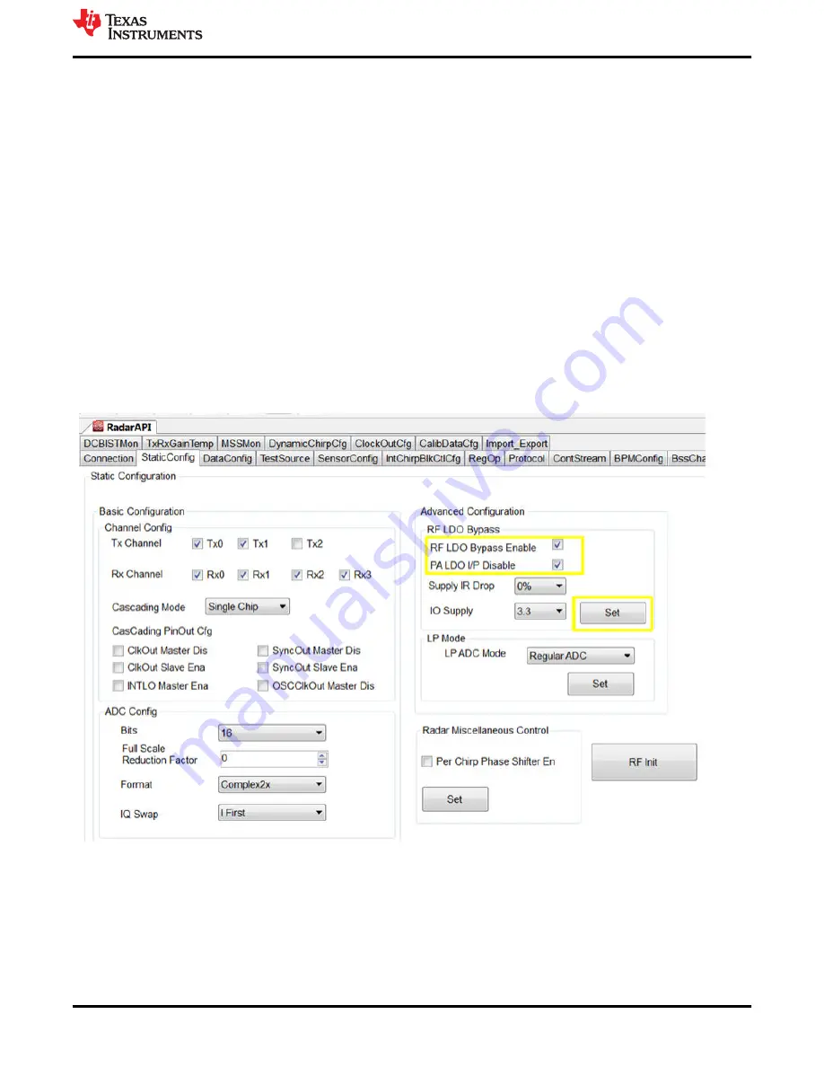
damage to the device, select the 'RF LDO Bypass Enable' and 'PA LDO I/P Disable' options in the Static
Configuration when using mmWave Studio. Additionally, the LDO bypass can be configured using the
AWR_RF_LDO_BYPASS_SB API. To enable the RF LDO Bypass and PA LDO I/P Disable through the API,
issue an ar1.RfLdoBypassConfig(0x3) command.
Figure 3-1. LDO Bypass Enable
Design Files and Software Tools
SPRUIX8 – MARCH 2021
AWR1843AoP EVM User’s Guide
27
Copyright © 2021 Texas Instruments Incorporated


