4.3 Complex Decimation Mode
The following software configuration steps will program the ADC366xEVM in Complex Decimation mode (32x)
with a 10 MHz analog input and 9.9 MHz NCO.
4.3.1 ADC35XX GUI: Complex Decimation Configuration
This procedure applies specifically to the ADC3663EVM, but can be applied to other sampling rates and bit
resolutions.
Table 4-3. 16-bit, Complex Decimation, Sample rate and DCLKIN examples
Interface Mode
DCLKIN multiplier
(Serialization Factor)
Example Sample Clock
Complex Decimation
Factor
Required DCLKIN
Frequency
2 Wire
4
65 MSPS
2
260 MHz
1 Wire
8
32 MSPS
8
64 MHz
1/2 Wire
16
10 MSPS
32
10 MHz
For this 32x Complex Decimation example, apply a 65 MHz signal to J9 (sample clock) and a 16.25 MHZ signal
to J7 (DCLKIN).
External ADC sampling clock source and DCLKIN source must be frequency locked. If this is not
performed, the captured data will appear scrambled. If using the onboard clocking option, the
sampling clock and DCLKIN are frequency locked.
Apply a 10 MHz signal to J2 (ensure bandpass filter is used to reduce harmonics and noise of signal generator).
An NCO of 9.9 MHz are used to shift the 10 MHz input signal to -100 kHz.
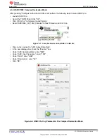
After launching the ADC35xxEVM GUI perform the following steps:
• Under "Resolution", select "16 bit".
• Under "Mode", select "2 Wire"
• Under "DDC", Select "Complex".
• For "Decimation Factor", select "32".
• Ensure that "CDC Enable" is red (disabled).
• To calculate the DCLKIN frequency, enter "65" in the Fs(MHz) field, and click calculate. This is informational
only.
• Under "FNCO A (MHz)" and "FNCO B (MHz)", enter "9.9" in the field. This field then calculates to the nearest
valid NCO value, and auto-calculates the correct register values in the field next to it.
• Click "Configure".
ADC GUI Configuration
16
ADC366xEVM Evaluation Module
SBAU366 – JANUARY 2021
Copyright © 2021 Texas Instruments Incorporated


