background image

User’s Guide 

SNAU120-April 2012 


ADC161S626BEB User’s Guide 


SNAU120-April 2012 


ADC161S626BEB User’s Guide  

LIST OF FIGURES ............................................................................................................. 1


LIST OF TABLES ............................................................................................................... 1


1.


INTRODUCTION ......................................................................................................... 1


2.


BOARD ASSEMBLY ................................................................................................... 1


3.


QUICK START ............................................................................................................ 3


4.


FUNCTIONAL DESCRIPTION .................................................................................... 4


5.


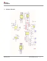
HARDWARE SCHEMATIC ......................................................................................... 5


6.


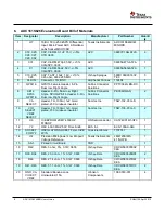
ADC161S626 EVALUATION BOARD BILL OF MATERIALS ................................... 6


EVALUATION BOARD/KIT/MODULE (EVM).................................................................. 11


LIST OF FIGURES


Figure 1: ADC161S626 Eval board connected to SPIO board.

 ..................................... 3


    LIST OF TABLES


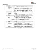
Table 1: Test Points on the ADC161S626 Evaluation Board

 ........................................ 2


Table 2: Connectors on the ADC161S626 Evaluation Board

 ....................................... 2


Table 3: Jumpers

 .............................................................................................................. 2


1. 

Introduction 

The ADC161S626BEB Evaluation Board Design Kit (consisting of the ADC161S626BEB board, this users 
guide, an optional SPIO4 board and an optional sensor board) is intended to ease evaluation of the 
ADC161S626.  With the optional SPIO4 board and optional Sensor board, the board allows evaluation of an 
entire Sensor AFE system. 
The evaluation board can be used in stand alone mode, in which the user interfaces with the part through the 
SPIO-GPSI16 connector and applies input signals on the AB12 connector.  The board can also be used with 
an SPIO4 board in place of an external pattern generator.  Finally, in the Sensor AFE system, the 
ADC161S626BEB board and the optional sensor board (for example, the LMP91000 Configurable AFE Gas 
Sensor board) can be used with an SPIO4 board to evaluate the entire Sensor AFE system. 

2. 

Board Assembly 

The ADC161S626BEB evaluation board comes fully assembled and ready for use. Refer to the Bill of 
Materials for a description of components and to the schematic at the end of this document.  There are 
jumper selections for choosing between different power supply and clock configurations. 


Содержание ADC161S626BEB

Страница 1: ...ase evaluation of the ADC161S626 With the optional SPIO4 board and optional Sensor board the board allows evaluation of an entire Sensor AFE system The evaluation board can be used in stand alone mode in which the user interfaces with the part through the SPIO GPSI16 connector and applies input signals on the AB12 connector The board can also be used with an SPIO4 board in place of an external pat...

Страница 2: ...the SPIO4 board GPSI16 16 pin dual row right angle female header Carries signals from the SPIO4 board to any optional SensorAFE board AB12 12 pin dual row right angle male header Carries analog bus signals from an external source or the optional Sensor AFE board to the ADC Table 2 Connectors on the ADC161S626 Evaluation Board Jumper Purpose VREF SELECT Selects reference source for VREF Settings ar...

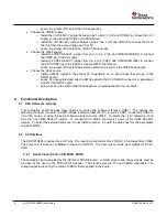
Страница 3: ... This will connect the ADC VREF line to the 4 096V on board LM4120 reference Ensure that a 4MHz crystal is installed in the socket Y2 and that there is no signal applied at the CLK IN BNC jack Connect the SPIO4 board to the ADC161S626BEB board at the SPIO GSPI16 male header Line up the white arrows on the bottom of the headers Connect the LMP91000 board to the GPSI16 and AB12 headers Line up the w...

Страница 4: ...to generate a clock for the SPIO4 board o Bring a clock to the SPIO GPSI16 header from an external board of your choice 4 Functional Description 4 1 ADC Reference Circuitry This evaluation board includes three options to source the voltage reference VREF The options are selecting the fixed on board 4 096V voltage reference LM4120 4 1 to source VREF connecting VREF to VA of the device or using the ...

Страница 5: ...SNAU120 April 2012 ADC161S626BEB User s Guide 5 5 Hardware Schematic ...

Страница 6: ...PIO GPSI16 Header 8 Pin Dual row Right Angle Sullins Connector Solutions PBC36DGAN 2 9 VA SELECT Header TH 100mil 1x2 Gold plated 230 mil above insulator Samtec Inc TSW 102 07 G S 1 10 VIO SELECT VREF SELECT Header TH 100mil 1x3 Gold plated 230 mil above insulator Samtec Inc TSW 103 07 G S 2 11 U6 IC EEPROM 2KBIT 400KHZ 8TSSOP ON Semiconductor CAT24C01WI GT3 1 12 Y2 OSC 4 000 MHZ 5 0V FULL SIZE EC...

Страница 7: ...gement of patents or services described herein Mailing Address Texas Instruments Post Office Box 655303 Dallas Texas 75265 Copyright 2012 Texas Instruments Incorporated REGULATORY COMPLIANCE INFORMATION As noted in the EVM User s Guide and or EVM itself this EVM and or accompanying hardware may or may not be subject to the Federal Communications Commission FCC and Industry Canada IC rules For EVMs...

Страница 8: ...armful interference in a residential installation This equipment generates uses and can radiate radio frequency energy and if not installed and used in accordance with the instructions may cause harmful interference to radio communications However there is no guarantee that interference will not occur in a particular installation If this equipment does cause harmful interference to radio or televi...

Страница 9: ... de brouillage radioélectrique à l intention des autres utilisateurs il faut choisir le type d antenne et son gain de sorte que la puissance isotrope rayonnée équivalente p i r e ne dépasse pas l intensité nécessaire à l établissement d une communication satisfaisante Le présent émetteur radio a été approuvé par Industrie Canada pour fonctionner avec les types d antenne énumérés dans le manuel d u...

Страница 10: ...技術基準適合証明を受けておりません 本製品のご使用に際しては 電波法遵守のため 以下のいずれかの措置を取っていただく必要がありますのでご注 意ください 1 電波法施行規則第6条第1項第1号に基づく平成18年3月28日総務省告示第173号で定められた電波暗 室等の試験設備でご使用いただく 2 実験局の免許を取得後ご使用いただく 3 技術基準適合証明を取得後ご使用いただく なお 本製品は 上記の ご使用にあたっての注意 を譲渡先 移転先に通知しない限り 譲渡 移転できないも のとします 上記を遵守頂けない場合は 電波法の罰則が適用される可能性があることをご留意ください 日本テキサス インスツルメンツ株式会社 東京都新宿区西新宿6丁目24番1号 西新宿三井ビル http www tij co jp ...

Страница 11: ... limited to input and output voltage current power and environmental ranges may cause property damage personal injury or death If there are questions concerning these ratings please contact a TI field representative prior to connecting interface electronics including input power and intended loads Any loads applied outside of the specified output range may result in unintended and or inaccurate op...

Страница 12: ...warranties for the associated TI product or service and is an unfair and deceptive business practice TI is not responsible or liable for any such statements TI products are not authorized for use in safety critical applications such as life support where a failure of the TI product would reasonably be expected to cause severe personal injury or death unless officers of the parties have executed an...

Страница 13: ...SNAU120 April 2012 ADC161S626BEB User s Guide 13 Mailing Address Texas Instruments Post Office Box 655303 Dallas Texas 75265 Copyright 2007 Texas Instruments Incorporated ...

Отзывы: