background image

Program Battery Memory Charge Settings

135

RangePro RPX8-P User Manual 

P • Using the D400 Charger with a RangePro RPX8-P Battery 

7.

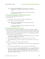
When all system settings for the channel have been properly set and verified, press the 

BATT/PROG

 “ ” 

button to return to the main menu.

8.

If not already completed, repeat steps 2 through 7 for the other charging channel.

Program Battery Memory Charge Settings

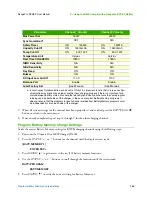
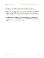
Verify the correct Battery Memory settings for BOTH charging channels using the following steps:

1.

Power-on the Ultimate Duo 400W Charger (D400).

2.

Press the 

STATUS

 “

+

” or “

-

” buttons for the channel until the display screen reads:

[BATT MEMORY 1]

            ENTER SET->

3.

Press 

ENTER

 “

” to gain access to the ten (10) battery memory locations.

4.

Use the 

STATUS

 “

+

” or “

-

” buttons to scroll through the locations until the screen reads:

BATT/PROGRAM

           BATT MEMORY

5.

Press 

ENTER

 “

” to verify the correct setting for Battery Memory 1.

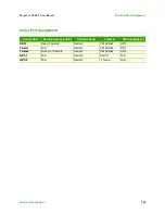
Parameter

Channel 1 Value(s)

Channel 2 Value(s)

Max Power Set

200W

200W

Synchronization

a

a. In most cases Synchronization can be set to 

ON

 but it is important to note that in rare cases Syn-

chronization may prevent one side or another from charging properly if there is a significant mis-
match between battery states. Also note that while Synchronization will ensure the same program 
is being used by both sides of the charger, in the case of custom Battery Memory programs it 
does not ensure that the programs for each channel are identical. Battery Memory programs must 
be independently set on each side of the charger.

OFF

N/A

Safety Timer

ON              150Min

ON              150Min

Capacity Cut-Off

ON        12600mAh

ON        12600mAh

Temp Cut-Off

ON           50C 122F

ON           50C 122F

Temperature Unit

Celsius

Celsius

Rest Time CHG\DCHG

10Min

10Min

NiMH Sensitivity

N/A

N/A

NiCd Sensitivity

N/A

N/A

Key Beep 

ON

ON

Buzzer

ON

ON

DC Input Low Cut-Off

11.0 V

11.0 V

Balance Port

Enable

Enable

Load Factory Set

(See Manual)

(See Manual)

Содержание RangePro RPX8-P

Страница 1: ...Manual For Pixhawk Ardupilot Flight Controlled Systems Toll Free 1 800 628 3119 Phone 1 301 263 7321 Support https terraview com contact Web www terraview com Document Number 50000094 T3IMD Rev A Rev...

Страница 2: ...a registered trademark of TerraView 360 Inc TerraView All other trademarks presented in this document are the property of their respective owners Copyright 2020 TerraView 360 Inc all rights reserved T...

Страница 3: ...Support 90 A Certifications Compliance 92 B Warranty 94 C RangePro RPX8 P Manual Flight Checklist 97 D RangePro RPX8 P Automated Flight Checklist 100 E RangePro RPX8 P Post Flight Checklist 102 F LED...

Страница 4: ...Summary Table of Contents 4 RangePro RPX8 P User Manual P Using the D400 Charger with a RangePro RPX8 P Battery 133...

Страница 5: ...Industry Standards 16 1 General Information 17 RangePro RPX8 Overview 18 Understanding Pixhawk and Ardupilot Open Source Autopilot Systems 18 2 What s in the Case 20 Introduction 21 Where is the Batte...

Страница 6: ...Station Setup 53 Setting Up the Ground Control Unit GCU 54 Mounting the Tablet onto the Tablet Holder 57 Connecting the Client Device to WiFi 60 Running the QGroundControl Application 61 Setting up Vi...

Страница 7: ...81 Uploading Parameter Files 81 QGroundControl 81 Mission Planner 81 Collecting On Board Flight Telemetry 82 QGroundControl 82 Mission Planner 82 Collecting Payload Data 82 10 Drone Battery Management...

Страница 8: ...Checklist 97 Preflight Checklist 98 Arm for Flight Takeoff and Control Validation 99 Landing 99 D RangePro RPX8 P Automated Flight Checklist 100 Preflight Checklist 101 Perform the Mission 101 Complet...

Страница 9: ...J Helpful Parameter Hints 117 General Ardupilot Settings 118 Aircraft Orientation During Autonomous Flight 118 Behavior During Return to Land 118 Herelink Specific 118 Trick for Tilting the Camera 11...

Страница 10: ...and Verify System Settings 134 Program Battery Memory Charge Settings 135 Balance Charge the Battery Using Battery Memory 1 136 Troubleshooting Common Charging Errors 137 The Channel Times Out Before...

Страница 11: ...legs 39 14 Raising the GPS antenna 40 15 Loosening wing fasteners 41 16 Rear arms unfolded 42 17 Lifting arm pins 42 18 All arms unfolded 43 19 Battery tester 44 20 Battery tester cable 44 21 Battery...

Страница 12: ...peller tips 69 42 Clear zone around UAV 70 43 UAV green and white position strobe lights 71 44 Manual Compass Calibration Initiation Sequence 72 45 Battery Status Display 72 46 Flight Safety Settings...

Страница 13: ...13 List of Tables 1 RangePro RPX8 P case contents 22 2 Power Out Pinout 126 3 Serial Out Pinout 127 4 Ethernet Out Pinout 127 5 I2C Out Pinout 128 6 SBus Out Pinout 128 7 PWM Out Pinout 128...

Страница 14: ...management Chapter 11 starting on page 87 provides maintenance procedures Chapter 12 starting on page 90 explains how to contact TerraView for support Appendix A starting on page 92 provides complianc...

Страница 15: ...mitter and the tablet as a combined system GCU Ground Control Unit The transmitter HUD Heads Up Display Payload Any gimbal and or sensor attachment connected to the RangePro RPX8 P RTH RTL Return to H...

Страница 16: ...or cannot find a particular document referenced below an elec tronic copy may be found on the www terraview com support page TerraView Flight Safety Manual SkyRC LiPoPal Instruction Manual Using the...

Страница 17: ...17 Chapter 1 General Information Chapter Contents RangePro RPX8 P Overview 18 Understanding Pixhawk and Ardupilot Open Source Autopilot Systems 18...

Страница 18: ...and landing manually or autonomously while supporting a wide range of payloads Highly portable and adaptable a complete system can be transported easily and can be oper ated by only one person The Ran...

Страница 19: ...aseline see section Uploading Parameter Files on page 81 Now that you have an overview of RangePro RPX8 P capabilities continue to Chapter 2 What s in the Case on page 20 Changing parameters can resul...

Страница 20: ...20 Chapter 2 What s in the Case Chapter Contents Introduction 21 Where is the Battery and Battery Charger 23 Spares and Replacements 23...

Страница 21: ...ing the button after the handle is at the desired length Figure 2 Case extension handle and release button Inspect the case for damage Open the case and verify that all equipment is secure and nothing...

Страница 22: ...ion RangePro RPX8 P Drone GCU Antennas Breakout Cable Set GCU Charger Ground Control Unit GCU Temporary Battery Stor age Areas remove the battery before shipping the case Battery Charging Cable Tablet...

Страница 23: ...rs In the event of a crash inspect your RangePro RPX8 P for damage including small cracks in the propellers and in the arms If a propeller is damaged it can be replaced with a spare propeller from the...

Страница 24: ...24 Chapter 3 Register Your Drone Chapter Contents Introduction 25 Label Your Drone According to FAA Regulations 25...

Страница 25: ...bsite at https faadronezone faa gov Label Your Drone According to FAA Regulations Comply with the current regulation for labeling your drone In the US refer to https faadronezone faa gov Now that you...

Страница 26: ...26 Chapter 4 Cautions and Warnings Chapter Contents Introduction 27 Motors and Propellers 27 The Aircraft 28 During a Flight 28 Shipping Lithium Polymer Batteries 28...

Страница 27: ...gloves or take other protective measures when touching the propellers Stay away from rotating propellers and motors Keep foreign objects away from rotating motors and propellers Power off the aircraft...

Страница 28: ...ent parts when servicing the UAV Perform regular maintenance on your aircraft and its components see Chapter 11 Maintenance on page 87 to ensure that everything is working properly To avoid the risk o...

Страница 29: ...Assemble RangePro RPX8 P for Flight Chapter Contents Introduction 30 Parts of the Aircraft 30 Aircraft Assembly 33 Battery Installation 43 Testing the Battery 43 Installing the Battery 46 Payload Ins...

Страница 30: ...he figure Front LED White Rear LED Green Accessory Platform Propeller Mount Screws Propeller Blade Screws GPS Antenna Raised The bottom view of the aircraft is shown in figure 5 on page 32 The followi...

Страница 31: ...o RPX8 P User Manual 5 Assemble RangePro RPX8 P for Flight The rear view of the aircraft is shown in figure 6 on page 33 The following are called out in the figure GPS Antenna Raised USB Access Port R...

Страница 32: ...Parts of the Aircraft 32 RangePro RPX8 P User Manual 5 Assemble RangePro RPX8 P for Flight Figure 5 Bottom view...

Страница 33: ...RangePro RPX8 P User Manual 5 Assemble RangePro RPX8 P for Flight Figure 6 Rear view Aircraft Assembly Do the following to assemble the UAV 1 Remove landing legs from the case see figure 7 on page 34...

Страница 34: ...er Manual 5 Assemble RangePro RPX8 P for Flight Figure 7 Removing landing leg from case Until the landing legs have been installed if you must place the UAV on a flat sturdy sur face do so carefully t...

Страница 35: ...le RangePro RPX8 P for Flight Figure 8 Removing RangePro RPX8 P drone from case 2 While gripping the RangePro RPX8 P firmly as shown in figure 8 carefully lift it from the case 3 Install a landing leg...

Страница 36: ...he landing leg into the socket until the pin engages the hole you may need to turn the leg in the socket until the pin aligns with the hole Figure 10 Installing a landing leg close up 5 Repeat steps 3...

Страница 37: ...st use 50 ohm cable terminated with standard SMA connectors not RP SMA Figure 11 Installing the antenna cables 7 Attach the antenna clip onto a landing leg as shown in figure 12 on page 38 Install bot...

Страница 38: ...ePro RPX8 P for Flight Figure 12 Attaching antenna clips onto landing legs 8 Install the second antenna cable onto the remaining radio antenna SMA connector shown in figure 11 on page 37 9 Attach the...

Страница 39: ...r Flight 10 Stand the drone on its legs on a sturdy flat surface as shown in figure 13 Figure 13 RangePro RPX8 P standing on landing legs 11 Rotate the GPS antenna mast to the upright position then ti...

Страница 40: ...User Manual 5 Assemble RangePro RPX8 P for Flight Figure 14 Raising the GPS antenna 12 Now you are ready to unfold the arms Turn the props out of the way then loosen the 4 wing fasteners about 1 4 tu...

Страница 41: ...ircraft Assembly 41 RangePro RPX8 P User Manual 5 Assemble RangePro RPX8 P for Flight Figure 15 Loosening wing fasteners 13 Unfold the rear arms being careful not to damage the propellers see figure 1...

Страница 42: ...arms unfolded 14 Lift arm pins see figure 17 and continue to rotate arms into position see figure 18 Make sure the arm pin clears the arm flange and inserts into the arm Wiggle arm slightly when the...

Страница 43: ...s are correctly positioned tighten the arm and pivot pins securely by hand The drone is assembled Continue to section Battery Installation Battery Installation Installing the battery consists of the f...

Страница 44: ...0 Battery tester cable 3 Connect the battery tester cable to the battery 4 Plug connector B1 into the battery tester as shown in figure 21 on page 45 position the connector so the black wire goes in t...

Страница 45: ...P if the variation between cells exceeds 0 1 volts Bal ance charging the battery typically results in all cells being within 0 03 volts of each other If the variation between cells exceeds 0 1 volts t...

Страница 46: ...the Battery Install the battery as follows 1 While pulling down the battery locking pin see figure 24 on page 47 slide the battery into the rails located under the fuselage When the locking pin is ju...

Страница 47: ...battery into the airframe rails 2 Continue inserting the battery into the rails until the spring loaded pin engages the battery transport mode hole see figure 25 Figure 25 Battery transport mode hole...

Страница 48: ...al support details contact https terraview com contact If you are installing a payload other than a Pixy U or Pixy F install it using payload specific instructions Oth erwise do the following to insta...

Страница 49: ...ur gimbal attach the gimbal ring to the gimbal plate as shown in figure 27 Figure 27 Installing gimbal ring onto gimbal plate 3 Attach the gimbal plate onto the aircraft by positioning the 4 mounting...

Страница 50: ...otate ring clockwise to locked icon 5 Rotate the ring clockwise from right to left until the alignment mark on the ring is aligned with the locked icon 6 If the payload such as the FLIR Duo Pro R requ...

Страница 51: ...e to Chapter 6 Ground Control Station Setup on page 52 Do not over tighten the GPS SMA connector to the FLIR camera When over tightened the SMA connector on the camera may come loose when attempting t...

Страница 52: ...Herelink Radio System Setup 53 Standard Ground Control Station Setup 53 Setting Up the Ground Control Unit GCU 54 Mounting the Tablet onto the Tablet Holder 57 Connecting the Client Device to WiFi 60...

Страница 53: ...s on the right nearer the camera trigger button Herelink radios are charged using a micro USB power connector The connector is hidden behind the rubber weather cover at the front of the unit Carefully...

Страница 54: ...trol Station Setup Setting Up the Ground Control Unit GCU Verify that the GCU is fully charged as follows 1 Remove the GCU see figure 30 from the case callout 7 in figure 3 on page 22 Figure 30 GCU An...

Страница 55: ...ation Setup Figure 31 Installing antennas on the GCU 2 Install the ground control unit antennas see callout 6 in figure 3 on page 22 for antennas location on the GCU as shown in figure 31 Never operat...

Страница 56: ...on to the ON position see figure 32 All 4 LEDs of the battery level indicator should be lit showing that the battery is fully charged see figure 33 Figure 32 GCU power switch Figure 33 GCU battery lev...

Страница 57: ...er input connector see figure 32 on page 56 7 Connect the GCU charger to an AC power outlet 8 When all 4 battery level indicators are lit see figure 33 disconnect the charger from the GCU 9 Store the...

Страница 58: ...User Manual 6 Ground Control Station Setup 2 Unfold the tablet holder see figure 36 Figure 36 Unfolded tablet holder 3 Grasp and lift the tablet holder clamp as shown in figure 37 on page 59 until the...

Страница 59: ...et Holder 59 RangePro RPX8 P User Manual 6 Ground Control Station Setup Figure 37 Lifting the tablet holder clamp 4 Place the tablet inside the clamp and adjust it to secure the tablet then release th...

Страница 60: ...ient Device to WiFi The GCS provides a WiFi connection for a client device This device can be any WiFi enabled device with a flight control software package such as QGroundControl Currently only one c...

Страница 61: ...nections Setting up Video Connections 1 Select the icon in the top left hand corner of the QGroundControl App 2 Select the General tab 3 Scroll down to the section titled Video 4 Set Video Source to R...

Страница 62: ...r 7 Emergency Procedures Chapter Contents Introduction 63 Propeller Loss 63 Loss of Power 63 Loss of GPS 64 Loss of Command and Control Link 64 Loss of Telemetry Data Link 64 Loss of Video Link 64 Fly...

Страница 63: ...TL sequence again Repeat this step until the aircraft comes home and lands 3 If the unit is not able to return to home manually land in the nearest unpopulated area 4 If the aircraft loses a propeller...

Страница 64: ...l bring the aircraft back to the takeoff location and automatically land 2 Ensure the landing area is clear and continue to monitor the aircraft and the surroundings for any danger ous situations that...

Страница 65: ...nction Fly Away Do the following 1 If the aircraft doesn t respond to any pilot inputs and is flying without pilot commands you may have a fly away situation 2 If this occurs note the battery voltage...

Страница 66: ...7 Ground Station Connection 71 Calibration 71 Battery Health Monitor 72 Flight Safety Settings 72 GPS Satellite Connectivity 73 Takeoff 74 In Flight 75 Landing 76 Post Flight 77 Disassemble the RangeP...

Страница 67: ...wing 1 Place the RangePro RPX8 P in a clear area absent of debris with direct access to satellites to obtain GPS lock 2 Unfold propellers so they are fully extended and perpendicular with props below...

Страница 68: ...ght Ops Figure 40 Positioning propellers for flight 3 Raise and secure the GPS antenna mast 4 Ensure the radio antennas connections are tight and the antennas secured to the legs 5 Ensure the payload...

Страница 69: ...en left and right arms tips as shown in figure 41 7 Check all propellers to verify the mounting flanges are secure to the motors and that the tension on the individual props is fairly tight 8 Check th...

Страница 70: ...attery until the locking pin engages the battery flight mode hole at which point the RangePro X8 will activate and power up The RangePro UAV will emit a series of beeps as part of the startup process...

Страница 71: ...rational 4 If applicable insert the SD card into the slot in the payload Calibration Newer versions of Ardupilot include a declination map and do not require recalibration of the compass at every new...

Страница 72: ...h Monitor Go into the battery status display by tapping on the battery icon at the top of the QGroundControl applica tion Verify that the battery voltage is about 20 volts the minimum takeoff voltage...

Страница 73: ...Settings GPS Satellite Connectivity Verify that there is sufficient GPS signal strength 10 or higher with an HDOP of 1 0 or lower to support flight operations on the QGroundControl app as shown in fig...

Страница 74: ...p Display HUD on the tablet to make sure all systems are in the green and ready to go 6 Ensure the aircraft is in the correct mode for your preferred flight operations TerraView recommends using Posit...

Страница 75: ...e com mands and verify that the aircraft responds as expected 4 Start a timer if needed 5 Double check the HUD for vitals and make sure all is correct Note the battery voltage and fly the drone to the...

Страница 76: ...ow the aircraft to land itself Keep in mind that the aircraft might veer off from the exact landing location Monitor the automated descent and make necessary lateral adjustments right control stick to...

Страница 77: ...the payload you are using 3 Fold the propellers and point them to the rear of the aircraft 4 Fold the arms as follows Loosen the pivot pin screw and loosen and lift the arm pins before attempting to f...

Страница 78: ...be tablet specific 2 Power down the ground controller setting the power switch to OFF 3 Remove the tablet from the client device holder 4 Loosen the locking lever then fold down the holder 5 Tighten...

Страница 79: ...n page 80 Verify that the battery or batteries have been removed from the temporary storage area in the case and or the drone before shipping the case See Appendix O Shipping Lithium Polymer Batteries...

Страница 80: ...oduction 81 Downloading Parameter Files 81 QGroundControl 81 Mission Planner 81 Uploading Parameter Files 81 QGroundControl 81 Mission Planner 81 Collecting On Board Flight Telemetry 82 QGroundControl...

Страница 81: ...is step saves the parameters in Mission Planner to a user defined file Uploading Parameter Files On occasion the best way to configure an aircraft is to load a parameter file The parameter file can in...

Страница 82: ...Mission Planner Select Data Data Flash Logs Download DataFlash Log via Mavlink select file s Download Selected Logs Mission Planner places the files in the default location C Users Documents Mission P...

Страница 83: ...83 Chapter 10 Drone Battery Management Chapter Contents Introduction 84 Charging the Battery 84 Inspecting the Battery 86 Storing the Battery 86 End of Life Battery Processing Steps 86...

Страница 84: ...rging the Battery Inspecting the Battery see page 86 Storing the Battery see page 86 End of Life Battery Processing Steps see page 86 Charging the Battery Do the following 1 Remove the battery charger...

Страница 85: ...rging cable see figure 53 from the case Figure 53 Battery charging cable 4 Connect the battery charging cable to the battery charger as shown in figure 54 Figure 54 Connecting the battery charging cab...

Страница 86: ...pins are secure and there are no burn marks See the document Ultimate Duo 400W Charger with a Range Pro X8 RP6S24KHDx Battery Pack Storing the Battery Charge batteries to their storage level See Ulti...

Страница 87: ...87 Chapter 11 Maintenance Chapter Contents Introduction 88 User Maintenance Activities 88 Replacing a Pair of Propellers 88...

Страница 88: ...there is no debris in the motors Inspect for damage to propellers loose screws and other unusual indications Replace damaged propellers Replace broken landing gear Tighten loose propeller mounts Tigh...

Страница 89: ...with a replacement screw from the plastic bag located in the case Leave the screw loose enough so that the propellers can easily be adjusted to accommodate the other screw 3 Install the second screw 4...

Страница 90: ...90 Chapter 12 Contacting TerraView for Support Chapter Contents Support Options 91...

Страница 91: ...ard warranty support TerraView offers training integration and customization services maintenance repair and extended warranty options Contact your distributor or sales representative for more informa...

Страница 92: ...tifications Compliance Chapter Contents Compliance 93 North America United States and Canada 93 FCC Part 15 Class B 93 NRTL Nationally Recognized Test Lab Mark 93 Standards 93 European Union 93 CE Mar...

Страница 93: ...to correct the interference by one or more of the following measures moving the equipment away from the receiver or re orienting the receiving antenna NRTL Nationally Recognized Test Lab Mark This de...

Страница 94: ...94 Appendix B Warranty Chapter Contents What Is Covered 95 What TerraView Will Do To Correct Problems 95 What This Warranty Does Not Cover 95...

Страница 95: ...e center TerraView will ship the repaired or replacement item s to you freight prepaid so long as you use an address in Canada or the U S excluding Puerto Rico and U S Possessions Shipments to other l...

Страница 96: ...ESENTATIONS MADE BY ANY OTHER PERSON OR FIRM ARE VOID EXCEPT AS PROVIDED IN THIS WRITTEN WARRANTY NEITHER TerraView NOR ITS AFFILI ATES SHALL BE LIABLE FOR ANY LOSS INCONVENIENCE OR DAMAGE INCLUDING D...

Страница 97: ...97 Appendix C RangePro RPX8 P Manual Flight Checklist Chapter Contents Preflight Checklist 98 Arm for Flight Takeoff and Control Validation 99 Landing 99...

Страница 98: ...the Strobe con trol switch on the GCS and observing a proper response from the aircraft 11 Verify data download to GCS 12 Verify camera image connection on GCS 13 Verify the Flight mode switch on the...

Страница 99: ...hrottle left gimbal upwards with authority giving maximum throttle until safely away from ground 3 5 meters 10 15 feet 5 Ensure unit is stable in a hover then cycle through small adjustments in all co...

Страница 100: ...100 Appendix D RangePro RPX8 P Automated Flight Checklist Chapter Contents Preflight Checklist 101 Perform the Mission 101 Completing the Mission 101...

Страница 101: ...the Mission 1 Slide bar to Start Mission 2 Be aware of automatic aircraft calibration at 5 10 meters 15 30 feet AGL Unit will pitch roll and wobble for a few seconds Take emergency action if it does n...

Страница 102: ...102 Appendix E RangePro RPX8 P Post Flight Checklist Chapter Contents Power Down Sequence 103 Safety Inspection 103 Payload Management 103 Stowing the Aircraft 103...

Страница 103: ...ear and landing gear brackets for cracks or structural defects 2 Inspect aircraft for debris or loose fasteners 3 Inspect propellers and propeller mounts for proper tightness 4 Remove debris from all...

Страница 104: ...104 Appendix F LED Meanings Chapter Contents Introduction 105...

Страница 105: ...BAS so should have better position estimate Solid green With single long tone at time of arming Armed GPS lock acquired Ready to fly Double flashing yellow Failing pre arm checks system refuses to arm...

Страница 106: ...d IP Addresses Chapter Contents Introduction 107 Herelink Systems 107 Important Settings Within QGroundControl 107 Standard Ground Control Station 107 GCS Client Configuration 108 Connecting to the Ra...

Страница 107: ...be found here http www hex aero wp content uploads 2018 11 HereLink Manual EN pdf One critical piece of information to retain is the Product Key that is provided with the unit That product key is requ...

Страница 108: ...extreme end of the commercial residential WiFi band on either channel 75 or 76 and power is set to the full 30 dBm In standard operations there is no need for a user to connect directly to either the...

Страница 109: ...ression rate be set to as low as possi ble to support a clear video display on the client screen Setting this number too high may result in drop outs and significantly worse video possibly even causin...

Страница 110: ...110 Appendix H Standard Controller Channel Numbers Chapter Contents Standard Controller Layout 111 Standard Controller Related Parameter Settings 112...

Страница 111: ...flight modes CH6 3 position momentary switch springs to center from both directions Usually used for zoom CH7 Momentary button usually used for camera trigger CH8 2 position switch usually used for de...

Страница 112: ...e 6 Zoom 3 Pos Momentary Switch or other To use for camera zoom Camera dependent To use for directly driving a servo SERVOxx_FUNCTION 56 RCIN6 7 Camera Trigger Momentary CAM_SERVO_ON 2000 do not chang...

Страница 113: ...bled SERVO11_FUNCTION 60 RCIN10 SERVO11_MAX 1900 SERVO11_MIN 1100 SERVO11_REVERSED 0 SERVO11_TRIM 1500 11 Strobe 2 Pos Switch Note Servo9 Aux1 typically wired to the strobe lights SERVO9_FUNCTION 61 R...

Страница 114: ...114 Appendix I Herelink Controller Settings Chapter Contents Herelink Controller Settings 115 Radio Tab 115 Joystick Tab 115 Button Tab 115 Channel Purpose and Effect 115 Hotspot 116...

Страница 115: ...B Short Press Toggle 1100 1900 12 1 C Short Press Toggle 1100 1900 10 1 D Short Press Toggle 1100 1900 11 1 CAM Short Press Momentary 1100 1900 7 1 Channel Purpose Associated Commands 5 Switch Betwee...

Страница 116: ...en high and low direct wired to Strobe Lights SERVO9_FUNCTION 61 12 Switch Servo10 Aux2 between high and low drives PWM 1 on FLIR setup SERVO10_FUNCTION 62 User selectable function on FLIR Item Value...

Страница 117: ...J Helpful Parameter Hints Chapter Contents General Ardupilot Settings 118 Aircraft Orientation During Autonomous Flight 118 Behavior During Return to Land 118 Herelink Specific 118 Trick for Tilting t...

Страница 118: ...e next waypoint WP_YAW_BEHAVIOR 3 descends rapidly LAND_SPEED_HIGH 4 until obtaining landing altitude LAND_ALT_LOW 5 then descends slowly LAND_SPEED 6 until landing is complete and the aircraft disarm...

Страница 119: ...119 Appendix K Configuration Specific Parameters Chapter Contents Load Specific Parameters 120...

Страница 120: ...OTOCOL 1 1 1 GPS2 Port A Disabled SERIAL5_PROTOCOL 1 1 1 GPS2 Port A Disabled SERVO1_FUNCTION 33 35 35 33 Motor1 Top Front Right 34 Motor2 Top Front Left 35 Motor3 Top Rear Left 36 Motor4 Top Rear Rig...

Страница 121: ...121 Appendix L Making Sense of Motor Tests Chapter Contents Making Sense of Motor Tests 122...

Страница 122: ...a motor test within Mission Planner the motors are identified alphabetically not numerically The table below shows the link between the Motor Location ID the Motor Test ID and the expected rota tiona...

Страница 123: ...123 Appendix M Serial Port Assignment Chapter Contents Serial Port Assignment 124...

Страница 124: ...Serial Port Assignment Carrier Port External Access Point Serial Channel Protocol SRx Assignment USB Rear of Aircraft Serial0 1 MAVlink1 SR0 Telem1 N A Serial1 2 MAVlink2 SR1 Telem2 Bottom of Aircraf...

Страница 125: ...Appendix N Breakout Board Connections and Pinouts Chapter Contents Introduction 126 Power Out 126 Serial Out 126 Ethernet Out 127 I2C Out 127 SBus Out 128 PWM Out 128 Related TerraView Breakout Cables...

Страница 126: ...draw of 5 Amps Connector ID J6 Breakout board connector Molex 1054301102 Mating connector Molex 1053071202 Mating connector crimp pins 1053001100 Pinout shown in table 2 Serial Out Extension of the T...

Страница 127: ...kout board connector JST SM05B GHS TB LF SN Mating connector JST GHR 05V S Mating connector crimp pins JST SSHL 002T P0 2 Pinout shown in table 4 I2C Out Extension of the I2C port on the carrier board...

Страница 128: ...crimp pins JST SSHL 002T P0 2 Pinout shown in table 6 PWM Out Extension of the PWM pins on the carrier board Connector ID J5 Breakout board connector JST SM08B GHS TB LF SN Mating connector JST GHR 08...

Страница 129: ...e wire leads 10000067 Aux to Pixy QuickConnect Eight pin JST to eight pin JST connector with pins 2 3 4 7 populated plugs into air craft connector with pins 4 5 6 7 popu lated plugs into QuickConnect...

Страница 130: ...130 Appendix O Shipping Lithium Polymer Batteries Chapter Contents Introduction 131 Basic Shipping Requirements 131...

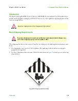
Страница 131: ...teries for return to TerraView or a third party the following basic requirements must be met 1 The shipping box must meet the U3480 regulation The packaging in which the batteries shipped is appropria...

Страница 132: ...igure 58 must also be present on the shipping container when shipping via air When shipping via ground this label is not required Figure 58 Cargo aircraft only label 4 Finally UN3480 covers shipping l...

Страница 133: ...arge Settings 135 Balance Charge the Battery Using Battery Memory 1 136 Troubleshooting Common Charging Errors 137 The Channel Times Out Before Charging is Complete 137 The Channel Stops Charging Due...

Страница 134: ...other Custom cable lengths are available upon request This appendix provides instructions on how to customize the D400 charger for use with the RP6S24KHDx battery as well as some common troubleshootin...

Страница 135: ...ify the correct setting for Battery Memory 1 Parameter Channel 1 Value s Channel 2 Value s Max Power Set 200W 200W Synchronizationa a In most cases Synchronization can be set to ON but it is important...

Страница 136: ...the Battery Memory screen and alternate between the following BATT MEMORY 1 BATT MEMORY 1 LiHV 22 8V 6S C 6 0A D 3 0A 10 Press the BATT PROG button to return to the main menu 11 If not already comple...

Страница 137: ...s properly installed Assuming there are no errors the display screen will alternate between the following R 6SER S 6SER R 6SER S 6SER CONFIRM ENTER CANCEL STOP 8 Press ENTER to proceed to the next ste...

Страница 138: ...nal Voltage Charge is reset to the default voltage for that battery type The user is not informed of this background change If the program is then saved without ensuring the TVC is set correctly the m...

Страница 139: ...only trickle charge at 0 1A until the battery reaches the minimum voltage threshold After all cells exceed the minimum voltage threshold the unit will switch to charging at full current until the pro...

Отзывы: