Standard Controller Layout
111
RangePro RPX8-P User Manual
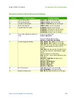
H • Standard Controller Channel Numbers
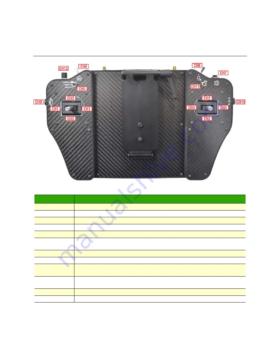
Standard Controller Layout
Figure 55. Standard Controller Layout
Channel
Description
CH1
Yaw Control
CH2
Pitch Control
CH3
Throttle Control
CH4
Roll Control
CH5
3-position switch, usually used for flight modes.
CH6
3-position momentary switch, springs to center from both directions. Usually used for
zoom.
CH7
Momentary button, usually used for camera trigger.
CH8
2-position switch, usually used for dedicated RTL.
CH9
90-degree Rotary dial. Range of motion with center detent. Usually used for gimbal
tilt.
CH10
90-degree Rotary dial. Range of motion with center detent. Usually used for gimbal
pan.
CH11
2-position switch, assigned to Strobes
CH12
6-position rotary dial with detents at each position.
Содержание RangePro RPX8-P
Страница 32: ...Parts of the Aircraft 32 RangePro RPX8 P User Manual 5 Assemble RangePro RPX8 P for Flight Figure 5 Bottom view...
Страница 90: ...90 Chapter 12 Contacting TerraView for Support Chapter Contents Support Options 91...
Страница 104: ...104 Appendix F LED Meanings Chapter Contents Introduction 105...
Страница 119: ...119 Appendix K Configuration Specific Parameters Chapter Contents Load Specific Parameters 120...
Страница 121: ...121 Appendix L Making Sense of Motor Tests Chapter Contents Making Sense of Motor Tests 122...
Страница 123: ...123 Appendix M Serial Port Assignment Chapter Contents Serial Port Assignment 124...
Страница 130: ...130 Appendix O Shipping Lithium Polymer Batteries Chapter Contents Introduction 131 Basic Shipping Requirements 131...

