Service and Repair Manual
December 2018
Manifolds
48
Z®-60/37 DC • Z®-60
/37 FE
Part No. 1271125GT
How t o Adj ust t he Pl atf or m Level U p R elief Val ve
How to Adjust the Platform Level
Relief Valves
Note: Perform this procedure with the machine in
the stowed position.
Platform Level Up
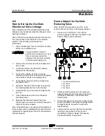
1
Connect a 0 to 5000 PSI / 0 to 350 bar
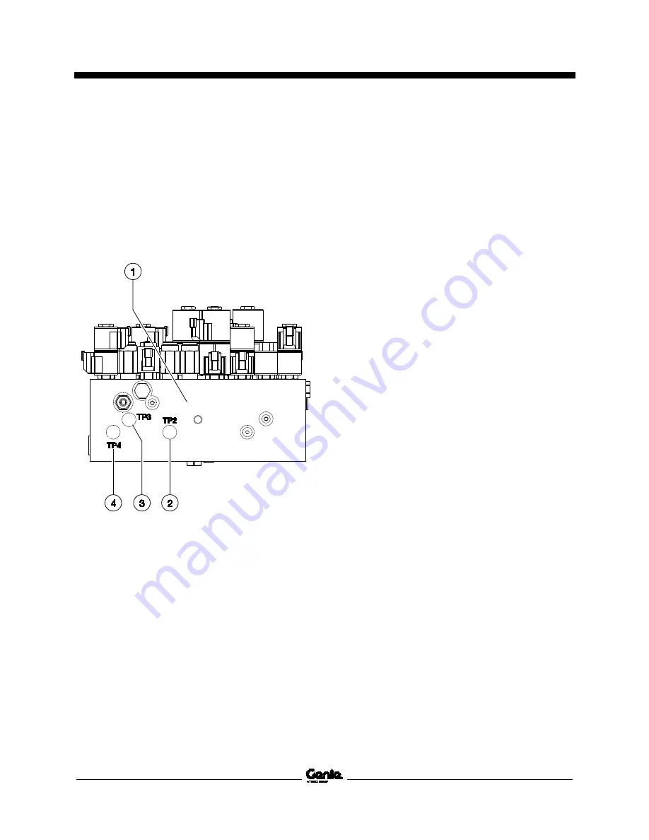
pressure gauge to test port 3 on the bottom of
the function manifold.
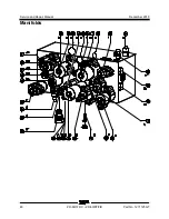
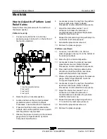
1 function manifold bottom
2 test port 2
3 test port 3
4 test port 4
2
Raise the jib to a horizontal position.
3
Locate and remove the solenoid operated
proportional valve coil. Refer to Repair
Procedures,
Function Manifold Components
.
4
Press and hold the function enable button.
Activate and hold the platform level up switch
with the platform fully elevated.
5
Observe the pressure reading on the pressure
gauge. Refer to Specifications,
Hydraulic
Component Specifications.
6
Locate and remove the cap from the platform
level up relief valve. Refer to Repair
Procedures,
Function Manifold Components.
7
Adjust the internal hex socket. Turn it
clockwise to increase the pressure or
counterclockwise to decrease the pressure.
Install the relief valve cap.
8
Repeat this procedure beginning with step 3 to
confirm the relief valve pressure.
9
Reinstall the proportional valve coil.
10 Remove the pressure gauge.
Platform Level Down
11 Connect a 0 to 5000 PSI / 0 to 350 bar
pressure gauge to test port 4 on the bottom of
the function manifold.
12 Raise the jib to a horizontal position.
13 Locate and remove the solenoid operated
proportional valve coil. Refer to Repair
Procedures,
Function Manifold Components
.
14 Press and hold the function enable button.
Activate and hold the platform level down
switch with the platform fully lowered.
15 Observe the pressure reading on the pressure
gauge. Refer to Specifications,
Hydraulic
Component Specifications
.
16 Locate and remove the cap from the platform
level down relief valve. Refer to Repair
Procedures,
Function Manifold Components
.
17 Adjust the internal hex socket. Turn it
clockwise to increase the pressure or
counterclockwise to decrease the pressure.
Install the relief valve cap.
18 Repeat this procedure beginning with step
11 to confirm the relief valve pressure.
19 Reinstall the proportional valve coil.
20 Remove the pressure gauge.
Содержание Genie Z-60 DC
Страница 54: ...Service and Repair Manual December 2018 Manifolds 44 Z 60 37 DC Z 60 37 FE Part No 1271125GT ...
Страница 56: ...Service and Repair Manual December 2018 Manifolds 46 Z 60 37 DC Z 60 37 FE Part No 1271125GT ...
Страница 104: ...Service and Repair Manual December 2018 CAN BUS Wiring Diagram DC Models 94 Z 60 37 DC Z 60 37 FE Part No 1271125GT ...
Страница 106: ...Service and Repair Manual December 2018 96 Z 60 37 DC Z 60 37 FE Part No 1271125GT This page intentionally left blank ...
Страница 107: ...December 2018 Service and Repair Manual 97 Wiring Diagram Options ...
Страница 108: ...Service and Repair Manual December 2018 98 Z 60 37 DC Z 60 37 FE Part No 1271125GT Wiring Diagram Options ...
Страница 110: ...Service and Repair Manual December 2018 100 Schematics Options 4WD DC and FE Models ...
Страница 111: ...December 2018 Service and Repair Manual 101 Power Cable Wiring Diagram ...
Страница 112: ...Service and Repair Manual December 2018 102 Z 60 37 DC Z 60 37 FE Part No 1271125GT Power Cable Wiring Diagram ...
Страница 113: ...December 2018 Service and Repair Manual 103 Hydraulic Schematic DC and FE Models ...
Страница 114: ...Service and Repair Manual December 2018 104 Z 60 37 DC Z 60 37 FE Part No 1271125GT Hydraulic Schematic DC FE Models ...
Страница 115: ...December 2018 Service and Repair Manual 105 Electrical Schematic DC FE Models ...
Страница 116: ...Service and Repair Manual December 2018 106 Z 60 37 DC Z 60 37 FE Part No 1271125GT Electrical Schematic DC FE Models ...
Страница 117: ...December 2018 Service and Repair Manual Part No 1271125GT Z 60 37 DC Z 60 37 FE 107 Electrical Schematic DC FE Models ...
Страница 118: ...Service and Repair Manual December 2018 108 Electrical Schematic DC FE Models ...
Страница 119: ...December 2018 Service and Repair Manual Part No 1271125GT Z 60 37 DC Z 60 37 FE 109 Electrical Schematic DC FE Models ...
Страница 120: ...Service and Repair Manual December 2018 110 Electrical Schematic DC FE Models ...
Страница 121: ...December 2018 Service and Repair Manual 111 Ground Control Box Terminal Strip Wiring Diagram DC FE Models ...
Страница 125: ......

