October 2018
Service and Repair Manual
Boom Components
Part No. 1268557GT
Z®-135
/70
89
11 While holding the hex-shaped key in position,
rotate the angle sensor mounting bracket
clockwise until it aligns with the machined
pocket. Do not allow the key to rotate while
holding it.
Note: Be sure the hex-shaped key remains
engaged in the sensor only.
12 Insert the hex-shaped key into the boom pivot
pin and the bracket into the machined pocket.
13 Install the angle sensor bracket retaining
fasteners.
14 Install the angle sensor cover and retaining
fasteners.
15 Connect the electrical connector to the new
sensor.
16 Calibrate the secondary boom angle sensor.
Refer to Repair Procedure,
How to Calibrate
the Secondary Boom Angle Sensor
.
How t o C alibr at e t he Sec ondar y Boom Angle Sensor
How to Calibrate the Secondary
Boom Angle Sensor
Note: If the axle sensor has been removed or
replaced, or the turntable level sensor has been
replaced, they must be calibrated first. Refer to
Repair Procedure,
How to Calibrate the Axle Angle
Senors
or
How to Calibrate the Turntable Level
Sensor
.
Tip-over hazard. Failure to
properly calibrate the machine
could cause the machine to tip
over resulting in death or serious
injury.
Note: For software versions 4.01 and higher, use
the 2 Point Calibration procedure. For software
versions before 4.01, use the 6 Point Calibration
Procedure. The software version is displayed on
the LCD screen when the red Emergency Stop
button is pulled out to the on position.
Note: A digital level will only be required to perform
the 6 Point Calibration procedure.
Note: A kit is available through Genie Product
Support (Genie part number 58351). This kit
includes a digital level with a magnetic base and
cable harnesses.
Note: Perform this procedure with the machine on a
firm, level surface with the booms in the fully stowed
position, in the drive enable zone and the axles fully
extended.
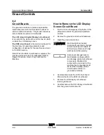
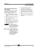
Note: Use the following chart to identify the
description of each LCD screen control button used
in this procedure.
Plus
Minus
Previous
Enter
Содержание Genie Z-135/70
Страница 13: ...October 2018 Service and Repair Manual Part No 1268557GT Z 135 70 13 This page intentionally left blank ...
Страница 14: ......
Страница 37: ...October 2018 Service and Repair Manual Specifications Part No 1268557GT Z 135 70 23 T ...
Страница 135: ...October 2018 Service and Repair Manual Manifolds Part No 1268557GT Z 135 70 121 ...
Страница 137: ...October 2018 Service and Repair Manual Manifolds Part No 1268557GT Z 135 70 123 ...
Страница 139: ...October 2018 Service and Repair Manual Manifolds Part No 1268557GT Z 135 70 125 ...
Страница 141: ...October 2018 Service and Repair Manual Manifolds Part No 1268557GT Z 135 70 127 ...
Страница 147: ...October 2018 Service and Repair Manual Manifolds Part No 1268557GT Z 135 70 133 ...
Страница 151: ...October 2018 Service and Repair Manual Part No 1268557GT Z 135 70 137 This page intentionally left blank ...
Страница 153: ...October 2018 Service and Repair Manual Manifolds Part No 1268557GT Z 135 70 139 ...
Страница 155: ...October 2018 Service and Repair Manual Manifolds Part No 1268557GT Z 135 70 141 ...
Страница 157: ...October 2018 Service and Repair Manual Part No 1268557GT Z 135 70 143 This page intentionally left blank ...
Страница 159: ...October 2018 Service and Repair Manual Manifolds Part No 1268557GT Z 135 70 145 ...
Страница 161: ...October 2018 Service and Repair Manual Manifolds Part No 1268557GT Z 135 70 147 ...
Страница 184: ...Service and Repair Manual October 2018 170 Z 135 70 Part No 1268557GT This page intentionally left blank ...
Страница 204: ...Service and Repair Manual October 2018 190 Z 135 70 Part No 1268557GT This page intentionally left blank ...
Страница 229: ...October 2018 Service and Repair Manual 215 Perkins 1104C 44 and 804D 33T Engine Electrical Schematic ...
Страница 232: ...Service and Repair Manual October 2018 218 Cummins B4 5L and B3 3T Engine Electrical Schematic ...
Страница 233: ...October 2018 Service and Repair Manual 219 Generator Wiring Schematic ...
Страница 234: ...Service and Repair Manual October 2018 220 Z 135 70 Part No 1268557GT Generator Wiring Schematic ...
Страница 235: ...October 2018 Service and Repair Manual Part No 1268557GT Z 135 70 221 Hydraulic Generator Welder Option ...
Страница 236: ...Service and Repair Manual October 2018 222 Hydraulic Generator Welder Option ...
Страница 237: ...October 2018 Service and Repair Manual 223 Hydraulic Schematic before serial number 180 except for serial number 102 ...
Страница 240: ...Service and Repair Manual October 2018 226 Hydraulic Schematic serial number 102 and from serial number 180 to 534 ...
Страница 241: ...October 2018 Service and Repair Manual Part No 1268557GT Z 135 70 227 Hydraulic Schematic from serial number 535 ...
Страница 242: ...Service and Repair Manual October 2018 228 Hydraulic Schematic from serial number 535 ...
Страница 244: ......


