February 2022
Service Manual
Checklist B Procedures
Part No. 1314708GT
GRC
™
21
B-7
Inspect the Tires, Wheels and
Castle Nut Torque
Genie specifications require that this procedure be
performed every 250 hours or quarterly, whichever
comes first.
Maintaining the tires and wheels, including proper
wheel fastener torque, is essential to safe
operation and good performance. Tire and/or
wheel failure could result in a machine tip-over.
Component damage may also result if problems
are not discovered and repaired in a timely
fashion.
1 Check the tire surface and sidewalls for cuts,
cracks, punctures and unusual wear.
2 Check each wheel for damage, bends and
cracks.
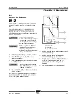
3 Remove the cotter pin and check the castle
nut for proper torque. Refer to Specifications,
Machine Specifications.
Note: Always replace the cotter pin with a new one
when removing the castle nut or when checking
the torque of the castle nut.
4 Install a new cotter pin. Bend the cotter pin to
lock in place.
B-8
Test the Drive Brakes
Genie specifications require that this procedure be
performed every 250 hours or quarterly, whichever
comes first.
Proper brake action is essential to safe machine
operation. The drive brake function should operate
smoothly, free of hesitation, jerking and unusual
noise. Hydraulically-released individual wheel
brakes can appear to operate normally when not
fully operational.
Note: Perform this procedure with the machine on
a firm, level surface that is free of obstructions.
Note: The platform extension deck must be fully
retracted and the platform in the stowed position.
1 Mark a test line on the ground for reference.
2 Turn the key switch to platform control and
pull out the red Emergency Stop button to the
on position at both the ground and platform
controls.
Note: Perform this procedure in high drive mode.
Verify the low speed drive light is off.
3 Choose a point on the machine (i.e., contact
patch of a tire) as a visual reference for use
when crossing the test line.
4 Bring the machine to top drive speed before
reaching the test line. Release the drive
joystick when your reference point on the
machine crosses the test line.
5 Measure the distance between the test line
and your machine reference point. Refer to
Specifications,
Performance Specifications
.
Note: The brakes must be able to hold the
machine on any slope it is able to climb.
Содержание Genie GRC-12
Страница 110: ...Service Manual February 2022 Wiring Diagram Ground and Platform Controls 98 GRC Part No 1314708GT...
Страница 113: ...February 2022 Service Manual 101 Electrical Schematic GRC Options...
Страница 115: ...February 2022 Service Manual 103 Electrical Schematic GRC from GRC11 1000 to GRC11 1078...
Страница 118: ...Service Manual February 2022 106 Electrical Schematic GRC from GRC11 1000 to GRC11 1078...
Страница 119: ...February 2022 Service Manual 107 Electrical Schematic GRC from GRC11 1079 to GRC14 1780...
Страница 122: ...Service Manual February 2022 110 Electrical Schematic GRC from GRC11 1079 to GRC14 1780...
Страница 123: ...February 2022 Service Manual 111 Electrical Schematic GRC from GRC14 1781 to GRC15 2343...
Страница 126: ...Service Manual February 2022 114 Electrical Schematic GRC from GRC15 2344 to GRC16P 2481...
Страница 127: ...February 2022 Service Manual 115 Electrical Schematic GRC from GRC16P 2482 to GRC16P 2562...
Страница 130: ...Service Manual February 2022 118 Electrical Schematic GRC from GRC16P 2563 to GRCP 5999...
Страница 131: ...February 2022 Service Manual 119 Hydraulic Schematic GRC from GRC11 1000 to GRC12 1168...
Страница 135: ......


