background image

Service Manual


February 2022


Specifications 


GRC


Part No. 1314708GT 


Hydraulic Hose and Fitting 

Torque Specifications 

Your machine is equipped with Parker Seal-Lok™ 

ORFS or 37° JIC fittings and hose ends. Genie 

specifications require that fittings and hose ends 

be torqued to specification when they are removed 

and installed or when new hoses or fittings are 

installed. 

Seal-Lok™ Fittings 

(hose end - ORFS) 

SAE Dash Size 

Torque 

-4 

18 ft-lbs / 25 Nm 

-6 

30 ft-lbs / 41 Nm 

-8 

40 ft-lbs / 55 Nm 

-10 

60 ft-lbs / 81 Nm 

-12 

85 ft-lbs / 115 Nm 

-16 

110 ft-lbs / 150 Nm 

-20 

150 ft-lbs / 205 Nm 

-24 

230 ft-lbs / 315 Nm 

JIC 37° Fittings 

(swivel nut or hose connection) 

SAE Dash Size 

Thread Size 

Flats 

-4 

7/16-20 

-6 

9/16-18 

1 1/2 

-8 

3/4-16 

1 1/2 

-10 

7/8-14 

1 1/2 

-12 

1 1/16-12 

1 1/4 

-16 

1 5/16-12 

-20 

1 5/8-12 

-24 

1 7/8-12 


SAE O-ring Boss Port 

(tube fitting - installed into Aluminum) 

(all types) 

SAE Dash Size 

Torque 

-4 

14 ft-lbs / 19 Nm 

-6 

23 ft-lbs / 31,2 Nm 

-8 

36 ft-lbs / 49 Nm 

-10 

62 ft-lbs / 84 Nm 

-12 

84 ft-lbs / 114 Nm 

-16 

125 ft-lbs / 169,5 Nm 

-20 

151 ft-lbs / 204,7 Nm 

-24 

184 ft-lbs / 249,5 Nm 


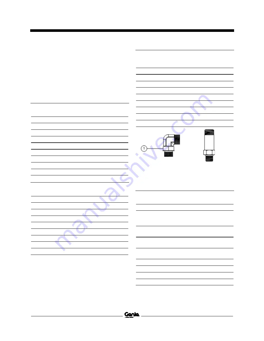
Adjustable Fitting 

Non-adjustable fitting 

1  jam nut 


SAE O-ring Boss Port 

(tube fitting - installed into Steel) 

SAE Dash Size 

Torque 

-4 

ORFS / 37° (Adj) 

ORFS (Non-adj) 

37° (Non-adj) 

15 ft-lbs / 20,3 Nm 

26 ft-lbs / 35,3 Nm 

22 ft-lbs / 30 Nm 

-6 

ORFS (Adj / Non-adj) 

37° (Adj / Non-adj) 

35 ft-lbs / 47,5 Nm 

29 ft-lbs / 39,3 Nm 

-8 

ORFS (Adj / Non-adj) 

37° (Adj / Non-adj) 

60 ft-lbs / 81,3 Nm 

52 ft-lbs / 70,5 Nm 

-10  ORFS (Adj / Non-adj) 

37° (Adj / Non-adj) 

100 ft-lbs / 135,6 Nm 

85 ft-lbs / 115,3 Nm 

-12  (All types) 

135 ft-lbs / 183 Nm 

-16  (All types) 

200 ft-lbs / 271,2 Nm 

-20  (All types) 

250 ft-lbs / 339 Nm 

-24  (All types) 

305 ft-lbs / 413,5 Nm 


Содержание Genie GRC-12

Страница 1: ...Service Manual Serial Number Range GRC 12 from GRC11 1000 to GRC16P 2369 from GRC16P 2370 to GRC16P 4599 from GRCP 4600 to GRCP 5999 Original Instructions Part No 1314708GT Rev A February 2022...

Страница 2: ...e 3 as defined by ISO 16368 Machine Design Life Unrestricted with proper operation inspection and scheduled maintenance Technical Publications Genie has endeavored to deliver the highest degree of acc...

Страница 3: ...ection Procedure Page Description A 2 2022 Initial Release Reference Examples Section Maintenance B 3 Electronic Version Click on any content or procedure in the Table of Contents to view the update S...

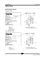
Страница 4: ...ber Legend To August 31 2016 1 Model 2 Model year 3 Facility code 4 Sequence number 5 Serial label behind covers 6 Serial number stamped on chassis From September 1 2016 1 Model 2 Facility code 3 Sequ...

Страница 5: ...manual are also safety hazards when maintenance and repair procedures are performed Do not modify or alter a MEWP without prior written permission from the manufacturer Do Not Perform Maintenance Unl...

Страница 6: ...azards such as moving parts free swinging or unsecured components when lifting or placing loads Always wear approved steel toed shoes Workplace Safety Any person working on or around a machine must be...

Страница 7: ...History iii Serial Number Legend 4 Section 1 Safety Rules v General Safety Rules v Section 2 Specifications 1 Machine Specifications 1 Performance Specifications 1 Hydraulic Component and Manifold Sp...

Страница 8: ...spect the Voltage Inverter if equipped 19 B 5 Test the Flashing Beacons 20 B 6 Test the Alarm Package if equipped 20 B 7 Inspect the Tires Wheels and Castle Nut Torque 21 B 8 Test the Drive Brakes 21...

Страница 9: ...chine Setup 37 2 3 Level Sensor 38 Hydraulic Pump 41 3 1 Hydraulic Pump 41 How to Remove the Hydraulic Pump 42 Function Manifold 43 4 1 Function Manifold Components 43 4 2 Valve Adjustments Function M...

Страница 10: ...Mast Components 58 10 1 Mast 58 How to Remove the Mast Assembly 58 How to Disassemble the Mast 60 How to Assemble the Mast 64 10 2 Wear Pads 70 10 3 Lift Cylinders 70 How to Remove the Lift Cylinder...

Страница 11: ...MAP 79 Operation Indicator Codes OIC 80 Diagnostic Trouble Codes DTC 80 Troubleshooting HXXX and PXXX Faults 81 Fault Inspection Procedure 82 Type HXXX Faults 84 Type PXXX Faults 85 Type UXXX Faults 8...

Страница 12: ...ectrical Schematics 103 Electrical Schematic GRC from GRC11 1000 to GRC11 1078 104 Electrical Schematic GRC from GRC11 1079 to GRC14 1780 108 Electrical Schematic GRC from GRC14 1781 to GRC15 2343 112...

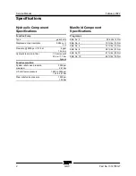
Страница 13: ...ing tank 2 2 gallons 8 3 liters Tires and wheels Tire size solid rubber 10 x 3 in 25 4 x 7 62 cm Castle nut torque lubricated 150 ft lbs 203 Nm Performance Specifications Drive speed maximum Platform...

Страница 14: ...tank return filter 10 micron with 25 psi 1 7 bar bypass Function manifold System relief valve pressure maximum 3500 psi 241 bar Lift relief valve pressure 1800 to 3500 psi 124 to 241 bar Steer relief...

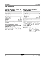
Страница 15: ...Note Genie specifications require additional equipment and special installation instructions for the approved optional fluids Consult Genie Product Support before use Optional fluids may not have the...

Страница 16: ...C Note Do not operate the machine when the ambient temperature is below 20 F 29 C with Rando HD Premium MV Chevron 5606A Hydraulic Oil Fluid Properties ISO Grade 15 Viscosity index 300 Kinematic Visco...

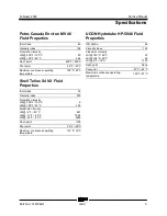
Страница 17: ...4 VX Fluid Properties ISO Grade 32 Viscosity index 300 Kinematic Viscosity cSt 200 F 100 C cSt 104 F 40 C 9 33 8 Brookfield Viscosity cSt 4 F 20 C cSt 13 F 25 C cSt 40 F 40 C 481 702 4 2624 Flash poin...

Страница 18: ...2 10 7 8 14 1 1 2 12 1 1 16 12 1 1 4 16 1 5 16 12 1 20 1 5 8 12 1 24 1 7 8 12 1 SAE O ring Boss Port tube fitting installed into Aluminum all types SAE Dash Size Torque 4 14 ft lbs 19 Nm 6 23 ft lbs...

Страница 19: ...ined properly 4 Position the tube and nut squarely on the face seal end of the fitting and tighten the nut finger tight 5 Tighten the nut or fitting to the appropriate torque Refer to the appropriate...

Страница 20: ...f flats for the proper tightening position Note The marks indicate the correct tightening positions have been determined Use the second mark on the body hex fitting to properly tighten the joint after...

Страница 21: ...nd scheduled may cause death serious injury or substantial damage Immediately tag and remove from service a damaged or malfunctioning machine Repair any machine damage or malfunction before operating...

Страница 22: ...tentially hazardous situation which if not avoided may cause minor or moderate injury Indicates a potentially hazardous situation which if not avoided may result in property damage Indicates that a sp...

Страница 23: ...wing chart to determine which group s of procedures are required to perform a scheduled inspection Inspection Checklist Daily or every 8 hours A Quarterly or every 250 hours A B Semi annually or every...

Страница 24: ...ualified service technicians according to the manufacturer s specifications and the requirements listed in the responsibilities manual Instructions Use the operator s manual on your machine The Pre de...

Страница 25: ...ep by step procedures in this section to learn how to perform these inspections If any inspection receives an N tag and remove the machine from service repair and re inspect it After repair place a ch...

Страница 26: ...c Return Filter A 2 Grease the Steer Yokes Genie specifications require that this procedure be performed every 100 hours of operation Regular application of lubrication to the steer yokes is essential...

Страница 27: ...lls with baking soda and water 1 Raise the platform to approximately 3 ft 1 m 2 Open the battery cover Rest the cover against the chassis 3 Lower the platform until the mast just contacts the battery...

Страница 28: ...er Note the results 13 Check the ambient air temperature and adjust the specific gravity reading for each cell as follows Add 0 004 to the reading of each cell for every 10 5 5 C above 80 F 26 7 C Sub...

Страница 29: ...alarm sounds and the LEDs blink one time correct the charger connections at the fuse and battery The charger will then operate correctly and begin charging the batteries If simultaneously the charger...

Страница 30: ...ontactor Limit switches 3 Inspect for a lite even coating of dielectric grease on all harness connections Note Do not apply excessive amounts of dielectric grease to harness connectors pins or sockets...

Страница 31: ...right fault LED 123 blinks one time the power draw is too high The tool being used requires too much power to operate or is being used at or near the limit of the inverter for an extended period of t...

Страница 32: ...d platform controls Result The beacons should flash 2 Turn the key switch to platform controls Result The beacons should flash B 6 Test the Alarm Package if equipped Genie specifications require that...

Страница 33: ...s or quarterly whichever comes first Proper brake action is essential to safe machine operation The drive brake function should operate smoothly free of hesitation jerking and unusual noise Hydraulica...

Страница 34: ...nt on the machine crosses the start line 4 Continue at full speed and note the time when the machine reference point crosses the finish line Refer to Specifications Performance Specifications B 10 Tes...

Страница 35: ...ple of hydraulic oil and place in a clear container Visually inspect the hydraulic oil for the following Color oil should be a clear light honey colored Appearance oil should be clear and not cloudy o...

Страница 36: ...dirty or clogged cap may cause the machine to perform poorly Extremely dirty conditions may require that the cap be inspected more often 1 Remove the breather cap from the hydraulic tank 2 Check for p...

Страница 37: ...ever comes first OR when the machine fails to lift the maximum rated load The hydraulic tank is a vented type tank The breather cap has an internal air filter that can become clogged or over time can...

Страница 38: ...he filter be replaced more often Beware of hot oil Contact with hot oil may cause severe burns Note The hydraulic tank return filter is mounted next to the hydraulic tank 1 Clean the area around the r...

Страница 39: ...aulic oil testing with an oil distributor If the hydraulic oil passes testing at the 2000 hour maintenance interval the oil must be tested every quarter by an oil distributor until the oil fails the t...

Страница 40: ...rn hard line into the tank Install the fitting onto the hydraulic filter head and torque to specification Refer to Specifications Hydraulic Hose and Fitting Torque Specifications 10 Fill the tank with...

Страница 41: ...erator s manual on your machine Be sure that all necessary tools and parts are available and ready for use Use only Genie approved replacement parts Read each procedure completely and adhere to the in...

Страница 42: ...nel to potential personal injury hazards Obey all safety messages that follow this symbol to avoid possible injury or death Indicates a imminently hazardous situation which if not avoided will result...

Страница 43: ...e the platform controls are used to operate the various machine functions The platform controls consist of an Emergency Stop button electronic circuit board proportional control handle drive steer ena...

Страница 44: ...rols LED Readout Code Condition LL Off Level CH Chassis Mode Operation PHS Pothole Guard Stuck Nd No Drive option CHrg Charger Interlock option Note A code and a description of a code can also be view...

Страница 45: ...ation Excessive torque of the circuit board fasteners will cause the buttons to bind Moderate torque of the circuit board fasteners will not allow the buttons to engage 1 2 Joystick How to Remove the...

Страница 46: ...e the alarm from the platform control box 1 4 Platform Emergency Stop Button How to Remove the Platform Controls Emergency Stop Button 1 Push in the red Emergency Stop button to the off position at bo...

Страница 47: ...he ECM This allows the platform to be raised or lowered at the ground controls Note Steer and drive functions are not available at the ground controls When the ECM is in the set up mode the ground con...

Страница 48: ...how CH See example below Result The display at the ground controls will show the machine model and hour meter information After 3 seconds the machine model will not show on the display See example bel...

Страница 49: ...eath or serious injury Tip over hazard This procedure must only be performed by a trained service professional Attempting this procedure without the necessary skills could result in death or serious i...

Страница 50: ...erform this procedure with the machine on a firm level surface that is free of obstructions Note Perform this procedure with the machine in the stowed position If you are not installing a new level se...

Страница 51: ...der the drive chassis at the ground controls side of the machine 9 Raise the machine approximately 2 inches 5 cm 10 Place a 0 65 x 6 x 6 inch 1 65 x 15 x 15 cm thick steel block under both wheels at t...

Страница 52: ...machine 29 Lower the machine onto the blocks 30 Raise the platform to approximately 1 ft 30 cm Result The level sensor alarm should not sound Result The level sensor alarm does sound The level sensor...

Страница 53: ...the key switch to ground control and pull out the red Emergency Stop button to the on position at both ground and platform controls 4 Activate the platform up function in one second intervals from th...

Страница 54: ...e pump Cap the fitting on the pump 2 Tag disconnect and plug the high pressure hose from the pump Cap the fitting on the pump Bodily injury hazard Spraying hydraulic oil can penetrate and burn skin Lo...

Страница 55: ...bs 24 Nm 3 Relief valve 1800 to 3500 psi 124 to 241 bar C Lift relief 20 ft lbs 27 Nm 4 Check valve 10 psi 0 7 bar D Drive circuit 20 ft lbs 27 Nm 5 Solenoid valve 3 position 4 way E Drive forward rev...

Страница 56: ...Service Manual February 2022 Function Manifold 44 GRC Part No 1314708GT Note alpha numeric callouts refer to corresponding notes on the electrical schematic...

Страница 57: ...s of the wheels at the steer end of the machine 4 Remove the platform controls from the platform 5 Turn the key switch to platform controls and pull out the red Emergency Stop button to the on positio...

Страница 58: ...efer to Specifications Machine Specifications 4 Turn the key switch to platform controls and pull out the red Emergency Stop button to the on position at both ground and platform controls 5 Remove the...

Страница 59: ...ction enable switch and press and hold the steer thumb rocker switch to the right Allow the wheels to completely turn to the right Continue holding the switch while observing the pressure reading on t...

Страница 60: ...ove all rings watches and other jewelry Note If the machine has been in operation allow the coil to cool at least 3 hours before performing this test 1 Tag and disconnect the wiring from the coil to b...

Страница 61: ...read 9V DC or more when measured across the terminals Resistor 10 Genie part number 27287 3 Set a multimeter to read DC amperage Note The multimeter when set to read DC amperage should be capable of...

Страница 62: ...5 1 Brake Release Hand Pump Components The brake release hand pump manifold is mounted behind the the hydraulic power unit Index No Description Schematic Item Function Torque 1 Hand pump J Manual brak...

Страница 63: ...ecifications Hydraulic Hose and Fitting Torque Specifications Perform this procedure with the platform in the stowed position 1 Tag disconnect and plug the hydraulic supply hard line at the pump Cap t...

Страница 64: ...the machine 5 Raise the machine approximately 2 inches 5 cm Place blocks under the chassis for support Crushing hazard The chassis will fall if not properly supported 6 Remove the wheel castle nut Re...

Страница 65: ...supported 6 Remove the wheel castle nut Remove the wheel 7 Tag disconnect and plug the hydraulic hoses on the drive motor Cap the fittings on the drive motor Bodily injury hazard Spraying hydraulic o...

Страница 66: ...rque specifications Drive motor mounting fasteners dry 75 ft lbs 101 7 Nm Drive motor mounting fasteners lubricated 56 ft lbs 76 3 Nm 8 2 Steer Cylinder How to Remove the Steer Cylinder Note When remo...

Страница 67: ...ing hazard The chassis will fall if not properly supported 4 Fully turn the yokes in either direction 5 Remove the fasteners securing the tie rod to the steer yoke Note Note the quantity and location...

Страница 68: ...ult in death or serious injury Remove all rings watches and other jewelry 5 Disconnect the platform controls from the control cable at the platform 6 Remove the platform controls from the platform 7 C...

Страница 69: ...ear pads to the side 3 Remove the fasteners securing the extension deck guide blocks to the extension deck and main deck Set the fasteners and the guide blocks to the side 1 extension deck latch 2 pla...

Страница 70: ...Hydraulic Hose and Fitting Torque Specifications Note Perform this procedure on a firm level surface with the machine in the stowed position 1 Remove the platform Refer to Repair Procedure How to Rem...

Страница 71: ...ly injury hazard Spraying hydraulic oil can penetrate and burn skin Loosen hydraulic connections very slowly to allow the oil pressure to dissipate gradually Do not allow oil to squirt or spray 10 Usi...

Страница 72: ...ove the fasteners securing the work trays to the upper half of the mast and remove the work trays Set the trays and the fasteners to the side 7 Remove the fasteners securing the down limit switch asse...

Страница 73: ...not enlarge the wear pad mounting holes Illustration 2 1 wear pads 2 rivet 3 mast number 4 4 mast number 3 5 mast number 2 6 mast number 1 12 Using a drill carefully drill out the rivets securing the...

Страница 74: ...s 2 rivet 3 mast number 3 4 mast number 2 5 mast number 1 16 Using a drill carefully drill out the rivets securing the number 2 outer wear pads to the top half of the number 2 mast section Refer to Il...

Страница 75: ...e number 1 outer wear pads to the top half of the number 1 mast section Refer to Illustration 2 Note While drilling the rivets out be careful not enlarge the wear pad mounting holes 21 Using a drill c...

Страница 76: ...ded 1 Thoroughly clean all mast sections 2 Attach a lifting strap from an overhead supporting device to the number 1 mast and place the number 1 mast onto a work table capable of supporting a complete...

Страница 77: ...alf of the number 2 mast and secure into place using the appropriate rivets Illustration 2 1 mast number 2 2 rivet 3 wear pads 4 mast number 1 7 Slide the number 2 mast towards the bottom of the numbe...

Страница 78: ...the number 2 mast with the cylinder mount brackets facing the work table Crushing hazard The mast section could become unbalanced and fall if not properly supported Note During installation the liftin...

Страница 79: ...ber 2 mast Refer to Illustration 6 Note After installing the first rivet move and align the number 3 mast access hole to the second hole on the wear pad and install the second rivet Illustration 6 1 w...

Страница 80: ...3 rivet holes Refer to Illustration 9 22 Working at the top of the number 4 mast carefully slide the lower corner wear pads between the number 4 mast and the number 3 mast Refer to Illustration 9 23...

Страница 81: ...to the mast assembly aligning the rod ends of the cylinder to the cylinder mast mounting brackets at the upper half of the mast assembly Crushing hazard The lift cylinder could become unbalanced and f...

Страница 82: ...s procedure requires specific repair skills lifting equipment and a suitable workshop Attempting this procedure without these skills and tools could result in death or serious injury and significant c...

Страница 83: ...t the clips to the side 6 Support the lift cylinder and use a soft metal drift to remove the mast cylinder pin from the lower mast assembly 7 Attach a lifting strap from an overhead supporting device...

Страница 84: ...ice Manual February 2022 Mast Components 72 GRC Part No 1314708GT 1 lift cylinder 2 manual lowering valve knob 3 coil 4 platform down solenoid valve 5 orifice 6 connector fitting 7 hydraulic hose asse...

Страница 85: ...er 2 4 cylinder number 1 5 cylinder wear block 10 5 Mast Coil Cord How to Remove the Mast Coil Cord Bodily injury hazard This procedure requires specific repair skills lifting equipment and a suitable...

Страница 86: ...rging profile must be programmed to match the specific battery type on the machine Charger status indicators 1 Error Fault USB indicator 2 AC power indicator 3 Battery charging indicator 4 USB port 5...

Страница 87: ...ne and battery type Refer to the chart below Profile Description P001 Flooded lead acid batteries Temperature compensated P003 Flooded lead acid batteries Not temperature compensated P007 Flooded lead...

Страница 88: ...ies 4 Secure the platform to an overhead lifting device 5 Carefully lift the platform approximately 3 feet 1 m Crushing hazard The platform will fall if not properly supported 6 Open the battery cover...

Страница 89: ...t equipment are available and ready for use Read each appropriate fault code thoroughly Attempting short cuts may produce hazardous conditions Be aware of the following hazards and follow generally ac...

Страница 90: ...pinpointing the area or component affected Models are listed below each code to assist in the troubleshooting codes for a specific model Genie SmartLink Diagnostic System This machine is equipped with...

Страница 91: ...QD32 03 Sensor power Digital Output Red J3 4 QD32 04 Automotive horn Digital Output White J3 5 QD32 05 Pothole limit switch Digital Input Orange Red J3 6 QD32 06 Machine ID Digital Input Red J3 7 QD32...

Страница 92: ...xamples of these devices are solenoid controlled hydraulic valves and motor controller Type PXXX Indicate a malfunction associated with power type devices in the electrical system The PXXX faults are...

Страница 93: ...Ground Controls and faulted device No Good Repair or replace harness an or connector Good No Good 3 Check GCON Electronic Control Module ECM Replace ECM Wiring Diagram The wiring diagram shown below...

Страница 94: ...actor Coil 47 OK Go to step 2 No Good Replace faulted device 2 Check the harness between the ground controls and the faulted device 1 Disconnect the GCON ECM connectors J1 QD31 J2 QD33 and J3 QD32 2 D...

Страница 95: ...fault code Refer to the GCON I O Map in this section to identify the faulted out circuit pin 3 Short to ground resistance should be greater than 5k 4 For short to B type faults measure resistance bet...

Страница 96: ...verse 1 circuit to battery positive Short circuit in drive reverse 1 harness Drive reverse 1 coil short circuit GCON ECM All functions inhibited except platform down H027 H027 COILFAULT DRIVE STEER RI...

Страница 97: ...T Short circuit of the automotive horn circuit to battery positive Short circuit in automotive horn harness Automotive horn short circuit GCON ECM Automotive horn inhibited P007 P007 DEVICEFAULT GCON...

Страница 98: ...ns inhibited U016 U016 SWITCHFAULT PCON STEER RIGHT Short circuit of the PCON steer right switch at system startup Short circuit of the PCON steer right switch GCON ECM All PCON drive and steer functi...

Страница 99: ...ystem startup Short circuit of the chassis digital tilt switch circuit Chassis digital tilt switch short circuit GCON ECM All functions inhibited except platform down as long as machine is in the elev...

Страница 100: ...oading software on device GCON ECM All functions inhibited C021 C021 PCON NOT DETECTED PCON not detected error PCON disconnected CAN communication failure GCON or PCON ECM All functions inhibited C023...

Страница 101: ...software revision connected to GCON with older software revision All functions inhibited C054 C054 GCON ECM FAULT TYPE 54 GCON ECM Fault Type 54 Short or open circuit to GCOM ECM GCON ECM All function...

Страница 102: ...s charger programming mode is active This will occur when the charger profile is being configured Type USB code Indicates the USB interface is active and the USB should not be removed This will occur...

Страница 103: ...er Fault Codes Fault Code Description Possible Causes Solution F 0 0 1 DC DC failure LLC excessive leakage fault Internal charger fault Disconnect AC input and battery pack for 30 seconds If fault doe...

Страница 104: ...t Charge output reduced due to high temperature Charge at lower temperature Check battery condition Replace damaged battery Check battery connections Battery pack deep discharge Disconnect battery pac...

Страница 105: ...from a different machine with different battery type Disconnect battery pack for 30 seconds to clear fault when condition has been corrected E 0 1 6 Software update failed Software update failed Confi...

Страница 106: ...45 65 Hz Self clearing when condition has been corrected E 0 2 4 Failure to initialize Charger failed to turn on correctly Disconnect AC input and battery pack for 30 seconds Contact Genie Product Su...

Страница 107: ...r ADC measurements triggered alarm Internal charger error Disconnect AC input and battery pack for 30 seconds Contact Genie Product Support E 0 3 2 CAN Bus heartbeat error CAN Bus heartbeat error CAN...

Страница 108: ...ules and operating instructions in the appropriate operator s manual on your machine Be sure that all necessary tools and test equipment are available and ready for use About This Section There are tw...

Страница 109: ...1 GCON ECM ground and platform controls J3 QD32 GCON ECM switches and sensors J2 QD33 GCON ECM function manifold QD34 Power buss switches and sensors QD35 Ground buss switches and sensors QD36 Pothole...

Страница 110: ...Service Manual February 2022 Wiring Diagram Ground and Platform Controls 98 GRC Part No 1314708GT...

Страница 111: ...h Limit switch N C H O Limit switch N O H C Circuits crossing no connection Emergency Stop button Motor Solenoid valve with diode Diode Circuit breaker Battery charger Level sensor Circuit connection...

Страница 112: ...d operated 2 position 4 way directional valve Check valve Fixed displacement pump Relief valve Solenoid operated 2 position 2 way directional valve normally closed with manual override Filter Bi direc...

Страница 113: ...February 2022 Service Manual 101 Electrical Schematic GRC Options...

Страница 114: ...12 GREEN J3 LED BEACON ALARM SENSOR V AUTO HORN MACHINE ID POTHOLE LIMIT SW DOWN LIMIT SW LOAD SENSE GROUND U1 LOAD SENSE GROUND LOAD SENSE GROUND THROTTLE 4 ENABLE 5 DC MOTOR CONTROLLER B B M U5 AUT...

Страница 115: ...February 2022 Service Manual 103 Electrical Schematic GRC from GRC11 1000 to GRC11 1078...

Страница 116: ...T SW DOWN LIMIT SW LEVEL SENSOR H5 H2 BR BR BR BR BR BR BR BR BR BR BR WH BK OR RD FB1 OR RD BK WH LS7 N C H O LS8 N C H O SENSOR V OUT RD MACHINE ID GR SELECT U1 GCON BR BR BR BR QD31 QD32 QD33 QD36...

Страница 117: ...V WH BL OR BR RD 1 2 3 4 5 6 1 2 3 4 5 6 7 8 9 10 11 12 1 2 3 4 5 6 7 8 U2 PCON QD47 BK YL BL YL GR BK WH RD WH E STOP E STOP P2 BL OR RD BK BK JOYSTICK AXIS 1 STEER SWITCH COM DRIVE ENABLE COM DRIVE...

Страница 118: ...Service Manual February 2022 106 Electrical Schematic GRC from GRC11 1000 to GRC11 1078...

Страница 119: ...February 2022 Service Manual 107 Electrical Schematic GRC from GRC11 1079 to GRC14 1780...

Страница 120: ...SOR H1 H2 BR BR BR BR BR BR BR BR BR BR BR WH BK OR RD FB1 OR RD BK WH LS7 N C H O LS8 N C H O SENSOR V OUT RD MACHINE ID GR SELECT U1 GCON BR BR BR BR QD31 QD32 QD33 QD35 QD36 QD39 RD BN RD BK V V SI...

Страница 121: ...H BL OR BR RD 1 2 3 4 5 6 1 2 3 4 5 6 7 8 9 10 11 12 1 2 3 4 5 6 7 8 U2 PCON QD47 BK YL BL YL GR BK WH RD WH E STOP E STOP P2 BL OR WH or RD BK BK JOYSTICK AXIS 1 STEER SWITCH COM DRIVE ENABLE COM DRI...

Страница 122: ...Service Manual February 2022 110 Electrical Schematic GRC from GRC11 1079 to GRC14 1780...

Страница 123: ...February 2022 Service Manual 111 Electrical Schematic GRC from GRC14 1781 to GRC15 2343...

Страница 124: ...ION Y5 Y6 Y3 Y4 Y7 Y8 GR GR WH WH BK WH BL BL BK OR BK OR BR BR BR BR BR BR WH BK WH BK OR RD WH BK V SIG V BR BR BL RD WH OR RD RD OR RD BK RD BR BR RD WH GR OR BR 1 2 3 4 5 6 1 2 3 4 5 6 7 8 1 2 3 4...

Страница 125: ...GR GR WH WH BK WH BL BL BK OR BK OR BR BR BR BR BR BR WH BK WH BK OR RD WH BK BR BR BL RD WH OR RD RD OR BR BR RD WH GR OR BR 1 2 3 4 5 6 1 2 3 4 5 6 7 8 1 2 3 4 5 6 7 8 9 10 11 12 PCONV E STOP DATA...

Страница 126: ...Service Manual February 2022 114 Electrical Schematic GRC from GRC15 2344 to GRC16P 2481...

Страница 127: ...February 2022 Service Manual 115 Electrical Schematic GRC from GRC16P 2482 to GRC16P 2562...

Страница 128: ...H WH BK WH BL BL BK OR BK OR BR BR BR BR BR BR WH BK WH BK OR RD WH BK BR BR BL RD WH OR RD RD OR BR BR RD WH GR OR BR 1 2 3 4 5 6 1 2 3 4 5 6 7 8 1 2 3 4 5 6 7 8 9 10 11 12 PCONV E STOP DATA LINK DAT...

Страница 129: ...ECH PRO LINK 1 V 2 GND 3 DATA LINK 4 DATA LINK D1 R1 200 10W H1 4 3 2 5 1 S7 TILT SENSOR V 1 GND 2 DATA LINK 3 DATA LINK 4 4 3 2 5 1 J6 5 DATA LINK 4 DATA LINK 3 E PCON STOP 2 V PCON 1 V PCON J5 ALARM...

Страница 130: ...Service Manual February 2022 118 Electrical Schematic GRC from GRC16P 2563 to GRCP 5999...

Страница 131: ...February 2022 Service Manual 119 Hydraulic Schematic GRC from GRC11 1000 to GRC12 1168...

Страница 132: ...BRAKE MANUAL RELEASE LEFT DRIVE MOTOR RIGHT DRIVE MOTOR FORWARD REVERSE M1 MOT 1 M4 MOT 4 HP HAND PUMP B BRAKE AC ACC S2 STEER 2 S1 STEER 1 V VENT L LIFT Y2 Y1 10 psi 0 7 bar 0 75 gpm 2 8 L min 1500 p...

Страница 133: ...RAKE MANUAL RELEASE LEFT DRIVE MOTOR RIGHT DRIVE MOTOR FORWARD REVERSE M1 MOT 1 M4 MOT 4 HP HAND PUMP B BRAKE AC ACC S2 STEER 2 S1 STEER 1 V VENT L LIFT Y2 Y1 10 psi 0 7 bar 0 75 gpm 2 8 L min 1500 ps...

Страница 134: ...Service Manual February 2022 122 Electrical Schematic GRC from GRC12 1169 to GRCP 5999 GRC Part No 131 470 8GT Service Manu al Feb rua ry 20 22...

Страница 135: ......

Отзывы: