


March 2022
Service Manual
Ground Controls
Part No. 1312899GT
GR
™
-20J • GR
™
-26J
61
Ground C ontrols
5-1 L evel Se nsor
5-1
Level Sensor
The tilt alarm sounds when the incline of the
chassis exceeds 2° to the side, front or rear.
How to Install and Calibrate the
Level Sensor
Tip-over hazard. Failure to install
or calibrate the level sensor as
instructed will compromise
machine stability and cause the
machine to tip over, resulting in
death or serious injury. Do not
install or calibrate the level
sensor other than specified in
this procedure.
Note: Perform this procedure on a firm, level
surface with the machine in the stowed position.
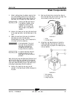
1 Open the turntable cover at the ground control
side of the machine.
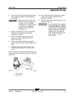
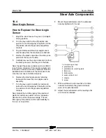
2 Locate the level sensor which is mounted on
the turntable base below the battery charger.
3 Tag and disconnect the level sensor pigtail
from the machine wire harness.
4 After noting the orientation of level sensor
assembly, remove the fasteners securing the
base of level sensor assembly to the chassis.
5 Install the new level sensor onto the machine.
Install and securely tighten the fasteners. Do
not over tighten.
6 Securely install the level sensor pigtail into the
machine wire harness.
7 Remove the plastic cap from the end of the
level sensor calibration wire.
8 Using a length of wire approximately
40 inches / 1 m long, connect the level sensor
calibration wire to the negative post of the
battery.
Electrocution/burn hazard.
Contact with electrically charged
circuits could result in death or
serious injury. Remove all rings,
watches and other jewelry.
Result: The green LED underneath the level
sensor flashes several times and stops. The
level sensor calibration is complete.
Result: The green LED underneath the level
sensor does not flash. Check the calibration
wire connection.
Note: The green LED is on during normal machine
operation and it only goes out when the tilt angle
of the machine exceeds 2°.
After the green LED stops flashing, disconnect the
calibration wire from the battery, and securely
install the plastic cap.
Содержание Genie GR-20J
Страница 12: ...Service Manual March 2022 xii GR 20J GR 26J Part No 1312899GT This page intentionally left blank ...
Страница 25: ...March 2022 Service Manual Part No 1312899GT GR 20J GR 26J 13 This page intentionally left blank ...
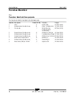
Страница 77: ...March 2022 Service Manual Function Manifold Part No 1312899GT GR 20J GR 26J 65 ...
Страница 113: ...March 2022 Service Manual 101 Electrica l Schemati cs Electrical Schematic GRJ from GRJL 2298 ...
Страница 116: ...Service Manual March 2022 104 Electrical Schematic GRJ from GRJL 2298 ...
Страница 117: ...March 2022 Service Manual 105 GCON LED Panel GRJ from GRJL 2298 ...
Страница 120: ...Service Manual March 2022 108 Temperature Sensor Harness GRJ from GRJL 2298 ...
Страница 121: ...March 2022 Service Manual 109 Options GRJ from GRJL 2298 ...
Страница 123: ...March 2022 Service Manual 111 Hydraulic Sc hema tics Hydraulic Schematic 2 2 kw from GRJL 2298 ...
Страница 127: ......


