background image


TD2303-08EN 

YTxx2 

54 

6.10.1  Tyre pressure and wheel load 

Every tyre displays information concerning its permissible load (load index) and speed 
(speed rating). The load index (e.g. 

152/147

) is a code for the maximum permissible load at 

the speed indicated by the speed rating (e.g. letter 

K

). The first number in the load index 

indicates the index for single mounting, the second for dual mounting. 
 
The tyre pressure should normally be 8 - 10 bar at nominal carrying capacity, depending on 
the tyre specification and load condition. The pressure for the tyre's load index is shown on 
the tyre sidewall. 
 
Speed rating (on tyre sidewall): F= 80km/h, G=90 km/h, J=100 km/h, K=110 km/h, 


     L=120 km/h, M=130 km/h). 


CAUTION


According to the ETRTO Standards Manual: 

“In any case, it is recommends to avoid the 

maximum permissible load capacity if the resulting inflation pressure is higher than 1000 
kPa (10 bar). In that case, either the load shall be reduced accordingly or the tyre and rim 
manufacturers shall be consulted.

” 


NOTICE


According to the ETRTO Standards Manual: "The load carrying capacity of tyres in dual 
fitments is twice the load carrying capacity in single up to 40 km/h. Bonus loads will not be 
permitted for speeds of 40 km/h and above if the wheel axles are rigidly fixed to the body of 
the vehicle." 

 
The relationship between load index and the maximum permissible tyre load is shown in the 
table below. 
 

Load index and load per tyre in kg 

(The tyre pressure for the load index is shown on the tyre sidewall) 

 Load index 

Load kg 


Load index 

Load kg 


Load index 

Load kg 

140 

2500 


160 

4500 


180 

8000 

141 

2575 


161 

4625 


181 

8250 

142 

2650 


162 

4750 


182 

8500 

143 

2725 


163 

4875 


183 

8750 

144 

2800 


164 

5000 


184 

9000 

145 

2900 


165 

5150 


185 

9250 

146 

3000 


166 

5300 


186 

9500 

147 

3075 


167 

5450 


187 

9750 

148 

3150 


168 

5600 


188 

10000 

149 

3250 


169 

5800 


189 

10300 

150 

3350 


170 

6000 


190 

10600 

151 

3450 


171 

6150 


191 

10900 

152 

3550 


172 

6300 


192 

11200 

153 

3650 


173 

6500 


193 

11500 

154 

3750 


174 

6700 


194 

11800 

155 

3875 


175 

6900 


195 

12150 

156 

4000 


176 

7100 


196 

12500 

157 

4125 


177 

7300 


197 

12850 

158 

4250 


178 

7500 


198 

13200 

159 

4375 


179 

7750 


199 

13600 


Содержание YT182

Страница 1: ...OPERATION MANUAL YT182 YT222 YARD TRACTOR DOCUMENT TD2303 08EN EDITION 01 2019 ...

Страница 2: ......

Страница 3: ...the wide range of engines and transmissions available a separate engine and transmission booklet has been prepared and has been provided at the back of the driver instructions Please read this carefully Terberg shall not be liable for any external equipment that does not form part of the supply contract All information markings and symbols on the tractor conform to general operator standards to th...

Страница 4: ...cture Engine Transmission Transfer case Front axle Rear axle Fifth wheel type Tyres Abbreviations and phrases AdBlue Diesel exhaust fluid Also known as DEF or Urea DIM Driver information Module ETRTO European Tyre and Rim Trading Organisation Regeneration Exhaust cleaning process to burn exhaust particulates using a high temperature This process can start automatically or manually SCR Selective Ca...

Страница 5: ...ional 22 4 Dashboard instruments 23 4 1 Main instruments 25 4 1 1 Ignition key 1 25 4 1 2 Parking brake 2 25 4 1 3 Trailer brake valve optional 2A 27 4 1 4 Gear lever 3 27 4 1 5 Combined direction indicator main dipped beam horn wipers 4 28 4 1 6 Fifth wheel levelling control 5 28 4 1 7 Additional hydraulic system option 6 28 4 2 Driver information module 7 29 4 2 1 Information on the Instrument P...

Страница 6: ...ears 47 5 2 4 Driving instructions 47 5 3 Tractor trailer un coupling 48 5 3 1 Using the lifting system of the 5th wheel 48 5 3 2 Coupling a trailer 49 5 3 3 Uncoupling a trailer 49 6 Daily maintenance 50 6 1 Fuel 50 6 1 1 Diesel 50 6 1 2 Natural gas 50 6 2 Engine Transmission oil level 50 6 3 Coolant level 51 6 3 1 Coolant 51 6 4 Hydraulic level 52 6 5 Fifth wheel 52 6 6 Air tanks and air dryer 5...

Страница 7: ... injury WARNING Indicates a potentially hazardous situation which if not avoided could result in death or serious injury CAUTION Indicates a potentially hazardous situation which if not avoided may result in minor or moderate injury NOTICE Throughout this manual you will see notes Notes will be used to show special procedures or point out important facts Notes will also designate important informa...

Страница 8: ...n the equipment of the vehicle and the nature of the work the training should cover all equipment and all tasks that have to be carried out by the driver All drivers must be suitably equipped with full safety clothing and footwear The minimum clothing requirements depend on local site regulations Terberg Benschop recommends wearing at least safety clothing that enhances driver visibility and safet...

Страница 9: ...ut high enough to provide sufficient clearance under the trailer and the load Ensure there is adequate ventilation especially while working in enclosed spaces While driving on ramps Ensure that ramps offer sufficient traction before driving onto them While driving on ramps always keep the fifth wheel as low as feasible select the correct gear and be aware of restrictions imposed by the maximum per...

Страница 10: ...rgency procedures Emergency exit from the cab In case of emergency you must be prepared to exit the tractor in the safest possible manner Drivers must be familiar with the methods of exiting their particular cab Doors must never be locked during operation It must be possible to enter or exit the cab quickly in case of emergency The possible exit points are 1 Via the side door 2 Via the side window...

Страница 11: ...peration of the Terberg tractor trailer combination on a flat horizontal surface the trailer should be kept in a horizontal position This to ensure that load distribution is optimal and stresses in the combination are kept to a minimum If the tractor is equipped with a hydraulic elevating fifth wheel the lifting frame must be raised sufficiently to ensure the trailer is at least parallel as shown ...

Страница 12: ...TD2303 08EN YTxx2 11 2 General lay out of the tractor Engine oil 5th Wheel Main switch Batteries Trailer connections Lifting frame AdBlue tank SCR DEF fluid Fuel tank Diesel ...

Страница 13: ... when entering the tractor to avoid personal injury Be careful at all times as the steps and decking might be slippery 3 1 1 Opening and closing the door Terberg recommends that the door be closed at all times to ensure safe operation To open Push in the door handle and open the door using the door handle and handrails provided until it locks in place To close Push in the door safety lock and clos...

Страница 14: ...djustment Pull the lever and adjust the angle by loading unloading the front and rear seat cushion area 5 Seat cushion rear angle adjustment Pull the lever and adjust the angle by loading unloading the rear and front seat cushion area 6 Backrest adjustment Pull the lever and adjust the backrest position while a load is applied to the backrest 7 Lumbar adjustment Air adjustment Press the button to ...

Страница 15: ... comfort 6 Seat cushion adjustment Pull the lever and move the seat cushion backwards or forwards Release the lever to lock the horizontal position 7 Damper adjustment The seat damping force can be adjusted to provide appropriate comfort for different road conditions Pull the lever to increase the damping force Push the lever to decrease the damping 8 Activate suspension It can be useful to depres...

Страница 16: ...te The legs must not be fully stretched when the accelerator or brake pedals are fully depressed 4 Adjusting the backrest steering wheel Press your shoulder against the backrest and hold your arm fully stretched on the steering wheel at 12 o clock Adjust the backrest to the preferred positions and maintain good visibility When this adjustment is finished your shoulder must still be against the bac...

Страница 17: ...ton highlighted here to adjust the seat damping force to provide appropriate comfort for different road conditions Pull the lever to increase the damping force and push it to decrease the damping 3 3 Passenger seat optional A passenger seat can be installed in the cab Before using the passenger seat Make sure the vehicle is at a complete standstill and apply the parking brake WARNING Always wear t...

Страница 18: ...ned along the drivers body For maximum protection avoid wearing the seat belt over voluminous clothing To release the seat belt grasp the belt and press the red button on the buckle Guide the belt with your hand and allow it to retract fully The belt will lock when it is pulled out quickly the vehicle is decelerating the vehicle is cornering The belt is intended for one person It must not be drawn...

Страница 19: ...This position should be used to provide rapid heating or cooling of the cab and to prevent unwanted dust entering the cab Using this position for longer periods of time is not recommended 3 5 3 Heating control This knob is the temperature control Turning it anti clockwise towards blue reduces the temperature and turning it clockwise towards red increases the temperature Avoid high temperatures in ...

Страница 20: ...esh air content by turning the air circulation control towards the fresh position Adjust the heating control and the blower speed as required Moderate climate 1 Turn the air conditioning off and turn the heating control to blue 2 Turn the circulation control to the fresh position 3 Adjust the blower as required High humidity and demisting Although the ambient temperature could be in the comfort zo...

Страница 21: ... the module is off the display backlight will be off and the temperature inside the cab will appear on the screen When the controller is turned on the main screen will appear 1 Air mix control 2 Mode 3 Desired temperature 4 Blower speed A symbol will be displayed if there is a fault in the system If this symbol appears refer to the service manual for further information Blower speed settings Press...

Страница 22: ...ctivated Heat The interior temperature is regulated by the electronic heater valve The A C compressor will remain off when heat mode is activated Demist defrost When defrost mode is activated the A C compressor is turned on the blower is at full speed and the heater valve is fully opened Air mix control Press the SET knob until the air circulation mode icon appears then turn the knob clockwise for...

Страница 23: ...st speed II blower runs at highest speed 3 8 Radio optional Check that the radio is working correctly and is tuned to the correct frequency channel for the site For more detailed information see the radio manufacturer s operating manual WARNING DO NOT have the radio volume too high this will expose the user to excessive noise and may lead to loss of hearing over a period of time ...

Страница 24: ... 10 M IR R O R R L 17 16 17 18 14 19 20 30 24 23 15 4A 2A 14A 5A 32 27 4A 7 2 2 1 3 1 2 1 0 2 1 3 28 1 F N R 0 J 0 I II 4 3 1 F N R 0 J 0 I II p 8 9 10 11 4 2 1 5 18 17 RHD 6 10 M IR R O R R L 17 16 17 18 14 19 20 30 24 23 15 4A 2A 14A 5A 32 27 4A 7 2 2 1 3 1 2 1 0 2 1 3 3 28 ...

Страница 25: ... 15 Air filter indicator light 16 Fifth wheel indicator light 17 Fifth wheel unlock buttons 18 Air suspension pressure release switch 19 Regeneration START switch optional 20 Regeneration STOP switch optional 21 Rear fog lamp switch optional 22 Electric outside mirror switch optional 23 Electric window switch optional 24 Heated outside mirror switch optional 25 Rear window heating optional 26 Heat...

Страница 26: ...atically resulting in sudden heavy braking 4 1 2 Parking brake 2 If the parking brake control is in the upper position tractor brakes not applied the parking brake can be engaged gradually If the control is in the lower position then the parking brake is applied warning light is illuminated and remains illuminated until the parking brake is released When the parking brake is applied the trailer br...

Страница 27: ...in motion as this is dangerous USA style brake system optional A yellow and red button can be mounted in the cabin as an alternative set up for the parking brake These buttons replace the regular controls for only the pneumatic parking brake Yellow button to apply the brakes of the tractor Red button to apply the brakes of the trailer For both buttons applies push to release and pull to apply the ...

Страница 28: ...nual for instructions Always maintain the engine at a comfortable operating speed by selecting the correct gear for the driving conditions When maximum engine performance is required ensure the engine is operating as close as possible to its maximum governed speed under load WARNING Shifting from forward 1 2 3 D to reverse and reverse to forward or shifting out of neutral position is only allowed ...

Страница 29: ...g the ring at the end of the handle operates the windscreen washer s 4 1 6 Fifth wheel levelling control 5 The lifting system is connected to the tractor s hydraulic system The fifth wheel can be adjusted to any desired height using control lever 5 Move the lever forward to lower the fifth wheel Move the lever back to raise the fifth wheel 4 1 7 Additional hydraulic system option 6 If the tractor ...

Страница 30: ...is connected to the vehicle s power supply and therefore does not have to be switched on or off manually Turn the ignition key to position 1 to activate the DIM CAUTION Only use the DIM menu when the vehicle is stopped and the parking brake has been applied Main Page Instrument Panel After start up the first page the Instrument Panel page appears on the DIM Exit to Instrument Panel Press the EXIT ...

Страница 31: ...the fuel level gauge will also monitor the level in the tank Fuel level is indicated by a white needle Urea level is indicated by a blue needle The small gauge on the right shows the air pressure in brake circuits 1 and 2 Brake circuit 1 front is indicated by a white needle Brake circuit 2 rear is indicated by a blue needle The character and digit in the middle of the tachometer indicate the statu...

Страница 32: ...menu Use button 4 and 5 to move the selected menu red box to one of the listed pages for example Instrument Panel and press button 1 OK to select the page In the main menu the next submenus are available 1 Dashboard Instrument panel 2 Numerical values 3 Display settings 4 Terberg Service Tools Only for authorized personnel 5 Error memory Button 2 Engine information Press button 2 engine icon to re...

Страница 33: ...mission convertor out oil temperature in C Button 4 Brake System information Press button 4 brake icon to request Brake System information Brake circuit 1 front pressure in bar Brake circuit 2 rear pressure in bar Button 5 Vehicle information Press button 5 vehicle icon to request Vehicle information Engine running hours ...

Страница 34: ...gh or too low STOP the engine immediately and do a check on the oil level YELLOW Engine fault code active A problem or a potential problem has been detected Have it checked or repaired Refer to the fault code in the engine service manual or refer to authorised service personnel YELLOW Engine coolant temperature is too high Stop the vehicle and engine as soon as possible to prevent damage YELLOW En...

Страница 35: ...ll be illuminated when the urea level is below 10 RED Fuel level low indication Together with the buzzer the tell tale flashes when the fuel level gets below 10 The buzzer can be suppressed by pressing the middle button of the display for 2 seconds Together with the buzzer the tell tale will illuminate continuously when the fuel level gets below 5 The buzzer cannot be suppressed in this situation ...

Страница 36: ... the water separator Open the drain valve manually until fluid drains out of the drain tube Drain the filter sump until clear fuel is visible YELLOW Air filter is contaminated Do replace the air filter element as soon as possible YELLOW Regeneration start switch This switch can be used to start a manual regeneration When the regeneration is manually started the SCR system cleaning light is illumin...

Страница 37: ...D Blinking light Tyre pressure is too low have the tyre pressure increased as quickly as possible by authorized personnel RED Solid light buzzer Tyre pressure in one of the tyres is critical Stop the vehicle as quickly as possible in a safe place and have the tyres checked by authorized personnel If there is no tyre failure check the TPMS system ...

Страница 38: ...ess Ok button 1 To scroll through the 3 pages of different values use button 4 and 5 Press button 2 Reset Trip to reset the Trip mileage to 0 on page 2 Display Settings Press one of the buttons for the information bar Press button 1 Main menu Select Display Settings with button 4 or 5 and press Ok button 1 Use button 5 to move the selector through the display settings The activated value will beco...

Страница 39: ...auses the direction indicators to flash simultaneously Hazard warning lights are used when you are forced to stop or park the vehicle where it might present a hazard or hindrance to other traffic The hazard warning lights can be used at any time irrespective of the position of the ignition switch 4 3 3 Work light switch 10 The work light is operated by pressing this switch 4 3 4 Rotating beacon sw...

Страница 40: ...disengaging the differential lock is allowed only when the vehicle is stationary Engage the differential lock before driving on surfaces with poor traction or on slippery roads Do not use the differential lock On surfaces that provide adequate traction When turning sharply or when the tractor is loaded When the vehicle is fitted with anti skid equipment snow chains etc Disengaging the differential...

Страница 41: ...h a trailer if the fifth wheel indicator is red 4 3 10 Fifth wheel unlock buttons 17 To unlock the fifth wheel the two buttons shown must be depressed simultaneously These buttons are located on the dashboard or in a location specified by the customer NOTICE If only one button is depressed it will not be possible to unlock the fifth wheel The locking mechanism must be checked for signs of wear whe...

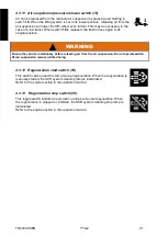
Страница 42: ...ING Ensure the vehicle is stationary before releasing air from the air suspension Do not operate switch 26 air suspension release while driving 4 3 12 Regeneration start switch 19 This switch can be used to start a manual regeneration When the regeneration is manually started the SCR system cleaning lamp is illuminated Refer to the engine section in the operation manual 4 3 13 Regeneration stop sw...

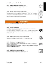
Страница 43: ...electric window by pressing the switch down Close the window by pressing the upper part of the switch The electric window is equipped with comfort control If the switch is held down for more than one second the window will automatically continue lowering until it reaches its end stop 4 4 4 Heated outside mirror switch optional 24 Heating for the outside mirrors is switched on by pressing switch 24...

Страница 44: ... stationary 4 4 9 Central greasing system lamp optional 29 The central greasing system is indicated on the dashboard by a lamp or a symbol The type of indication depends on the central greasing system that is installed In most cases the lamp shows the status and fault codes of the greasing system by means of flashing codes Normally when the ignition is set to the ON position the lamp flashes to in...

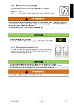
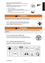
Страница 45: ...th local environmental regulations 4 4 11 Hydraulic system warning light optional 32 Yellow warning light 31 illuminates when a fault occurs in the hydraulic system e g high oil temperature WARNING If the warning light illuminates stop the vehicle as soon as possible Let the hydraulic system cool down by not using it The fault must be resolved by authorized service staff when the light remains ill...

Страница 46: ...rly the indicator on the dashboard will light up and a buzzer will sound when the tractor speed exceeds 1km h WARNING If the warning light illuminates and the buzzer sounds return the tractor to the workshop as soon as possible The cab lock bolt must be tightened by authorized service staff when the light illuminates and the buzzer sounds The operator is responsible for the safe use of the tractor...

Страница 47: ...tandards DIN 51601 EN590 or ASTM D975 No 2 D Check the AdBlue level Adjust driving position seating steering column Adjust the mirrors 5 2 Driving 5 2 1 Starting the engine Start the engine in the following order Ensure the parking brake is applied Ensure the gear lever is in neutral Turn the ignition key to the first position drive preheating Wait until this white engine wait warning light exting...

Страница 48: ...edal Ensure the tractor is standing completely still Do not press the throttle pedal the engine must be running idle Shift the gearbox in drive or reverse with the gear lever If the chosen gear is indicated on the DIM the tractor is ready for driving off Gently release the brakes as the tractor tends to drive off Press the throttle pedal for further acceleration WARNING To avoid unexpected vehicle...

Страница 49: ...t drive at excessive speed Do not allow the engine to idle unnecessarily Never leave the tractor for prolonged periods with the engine running 5 3 Tractor trailer un coupling 5 3 1 Using the lifting system of the 5th wheel The tractor has a lifting system for its 5th wheel due to ergonomic reasons for the driver The system is able to lift trailers of different heights so the driver doesn t have to...

Страница 50: ...by visual inspection or by carrying out a pull and push test to confirm that correct locking has taken place The vehicle must not be used until all the above conditions are checked 5 3 3 Uncoupling a trailer Find a suitable parking place and stop Lower the fifth wheel until the trailer front supports are on the ground Disconnect air lines and electrical connections between the trailer and the vehi...

Страница 51: ...tions Use special winter fuels for quick starting in winter 6 1 2 Natural gas For all natural gas engines the methane number based on SAE 922359 and the higher or lower heating value as appropriate must equal or exceed those shown in the table below Standard CES 14624 ISL G Minimum Methane number 75 Minimum Lower Heating value 37448 6 kJ kg 16100 BTU lbm NOTICE It is extremely important that fuel ...

Страница 52: ... toxic Hands must ALWAYS be washed after handling glycol Dispose of glycol in the proper manner WARNING When working on the cooling system care must be taken particularly if the engine is at operating temperature as the coolant may be hot enough to scald Always allow the system to cool down before removing the expansion tank cap Do not remove an expansion tank cap from a hot cooling system The coo...

Страница 53: ...ay up the sight glass when the lifting system is in its lowest position If the oil level is too low top it up with the same type of oil that is already present in the system Add oil through the breather filter on the top of the hydraulic tank Unscrew the breather filter cover anti clockwise and remove the breather filter Add oil into the hydraulic reservoir Replace the breather filter and screw th...

Страница 54: ...just the seat and mirrors to the correct positions before driving 6 9 Windscreen washers Check the fluid level and top up if required The reservoir is located in the cab In the summer add screen cleaner to the water reservoir to keep the windscreen free of greasy deposits and insects In winter use water mixed with special screen wash anti freeze 6 10 Wheels and tyres Check the condition and pressu...

Страница 55: ...d rim manufacturers shall be consulted NOTICE According to the ETRTO Standards Manual The load carrying capacity of tyres in dual fitments is twice the load carrying capacity in single up to 40 km h Bonus loads will not be permitted for speeds of 40 km h and above if the wheel axles are rigidly fixed to the body of the vehicle The relationship between load index and the maximum permissible tyre lo...

Страница 56: ...ity also shown in the following table When the wheel load exceeds the nominal rating the tyre pressure must be increased by factor L in accordance with the following table ONLY VALID FOR Speed rating F G J K L M Vehicle speed Carrying capacity Air pressure D L 50 1 12 1 08 40 1 15 1 10 30 1 25 1 13 25 1 35 1 17 20 1 50 1 21 15 1 65 1 25 10 1 80 1 30 5 2 10 1 40 0 2 50 1 40 D carrying capacity mult...

Страница 57: ... no persons or loose objects in the cab that could cause damage The windscreen washer reservoir is properly closed Some models are equipped with an additional steel strut to support the cab when it has been tilted This red strut is located next to the driver s seat WARNING If the safety bolt is not inserted in the rear cab support the cab may be liable to tilt during driving This could result in s...

Страница 58: ... been left under the cab Pump the cab down to its lowest position Keep pumping until pump resistance is felt Refit and secure the safety lock bolt Return the cab tilt bar to the storage position The lever on the hydraulic pump must be in the down position arrow down when driving 7 2 2 Electric cab tilting optional The electric cab tilting system is identified by the electrical box with 2 pushbutto...

Страница 59: ...lever on the hydraulic pump to the up position about 1 4 turn clockwise to the stop arrow up The system can be operated electrically by pressing the pushbutton 2 The cab will rise automatically The system can still be operated manually by pumping the cab with the manual hydraulic pump 2 Pump the cab until it has reached its maximum up position Secure the cab with the locking bar with a 6 mm retain...

Страница 60: ...be used to start or stop the engine when the cab is in the tilted position Procedure Ensure the transmission is in neutral Ensure the parking brake is applied Leave the ignition on The engine can be started using the START button The engine can be stopped using the STOP button 7 4 Electrical equipment Set the main switch to the OFF position when you do any maintenance on the electrical system of t...

Страница 61: ...t to disconnect all the electronics do the procedure as follows 1 Open the cover of one of the emergency switches manually 2 Set the switch to the OFF position manually anti clockwise rotation 3 The engine will stop and all the electronics will be disconnected Make sure that the situation is safe before you set the switch to the ON position again Do close the cover manually WARNING Do open the cov...

Страница 62: ...f the starter and the negative terminal of the battery to the negative terminal of the starter The negative lead should always be disconnected first and connected last e g when changing a battery This avoids the risk of short circuits WARNING Explosive gases can be released from a battery during charging Do not expose cell vents to an open flame risk of explosion Remove all the screw caps from bat...

Страница 63: ...ftboom 4 5 A solenoid engine stop 5 5 A supply 15 control lights combi instrument 6 5 A differential lock gear shift blocking F R 7 15 A air conditioning heater 8 10 A supply relay D start inhibitor 30 master instrument 9 10 A rotation warning light working lights air suspension 10 10 A windscreen wipers washers horn switch 11 5 A parking light right 10A optional 12 5 A parking light left instrume...

Страница 64: ...t accurate method is by means of a workshop beam setter 2 By some measurements as follows Check that the tyres are inflated as specified and position the unladen tractor on a level surface in front of a light coloured wall at a distance of 10 m Switch on the dipped beams Measure the vertical distance of the centre of the lamp units to the ground H and mark this height on the wall Check the data pl...

Страница 65: ... e rs e a n d re v e rs e to fo rwa rd o r s h iftin g o u t o f n e u tra l is ONL Y a llo we d wh e n th e tra c to r is s ta n d in g c o mp le te ly s till a n d e n g in e id le Ap p ly b ra k e s to s h ift fro m fo rwa rd to re v e rs e a n d re v e rs e to fo rwa rd S hi fti ng T24065315 ...

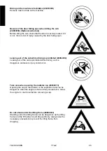
Страница 66: ...ed 24064004 Leaning out of the cab is prohibited while driving as it is dangerous and severe injury could occur Take care when opening the radiator cap 24064013 Opening the cap on the radiator or the expansion tank can be dangerous when the engine is hot and may cause burns Allow the engine to cool down before removing a cap Do not stand under the lifting frame 24064022 Standing under the lifting ...

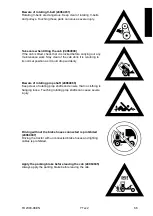
Страница 67: ... of the cab while it is returning to its normal position as it could drop suddenly Beware of rotating prop shaft 24064069 Keep clear of rotating prop shafts and ensure that no clothing is hanging loose Touching rotating prop shafts can cause severe injury Driving without the brake hoses connected is prohibited 24064087 Driving the tractor with unconnected brake hoses and lighting cables is prohibi...

Страница 68: ...ers equipped with a 3 king pin may be coupled Always keep manual safety lock of 5th wheel in locked position when driving on public road 24065896 Optional If the vehicle is prepared for driving on public roads the 5th wheel is equipped with a manual safety lock Always keep the manual safety lock of the 5th wheel in locked position when driving on public road Attention read the driver s instruction...

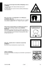
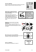
Страница 69: ...o reverse reverse to forward and out of neutral Retighten the wheel nuts after tyre change T24063856 After a tyre change or new vehicle delivery it is absolutely necessary to tighten the wheel nuts in the correct order after maximum 50 kilometers or 8 hours of operation Main electrical power switch T24063302 Use the main switch to switch battery current on by turning it clockwise or off by turning...

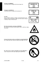
Страница 70: ...he cooling system Make sure that coolant is filled at a maximum rate of 10 liter minute Warning flammable substances 24066784 Be careful as the tractor contains liquids fuels etc which are highly flammable Parking the tractor inside is prohibited overnight 24066785 Do not park the tractor inside overnight as calamities can occur Do not use fire or a source of ignition near the LNG tank or other co...

Страница 71: ...ximum delivery and operating pressure of the LNG fuel station is 16 bar Do not step on this surface 24066843 It is not safe to walk or stand on the surface the sticker is placed It can either be slippery or not strong enough to stand on Hot surface Do not touch T24066858 ...

Отзывы: