IB 340513 (10-01)
1
No. 340513
Machine: 5700
Published: 10-01/00
System: SCRUBBING
INSTRUCTION BULLETIN
NOTE: DO NOT DISCARD the Parts List from the Instruction Bulletin. Place the Parts
List in the appropriate place in your machine manual for future reference.
Retaining the Parts List will make it easier to reorder individual parts and will
save you the cost of ordering an entire kit.
NOTE: Numbers in parenthesis ( ) are reference numbers for parts listed in Bill of Materials.
Installation instructions for kit number 374132
SYNOPSIS / PROBLEM:
This kit contains the parts needed to replace the solution control system on the model 5700
scrubber.
Please follow step-by-step instructions.
SPECIAL TOOLS / CONSIDERATIONS: NONE
(Estimated time to complete: 1 hour)
PREPARATION:
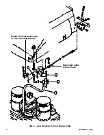
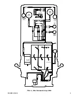
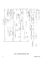
(Refer to FIG. 1 thru 4)
1. Empty the machine solution tank.
2. Move the machine to a clean level surface.
FOR SAFETY: Before leaving or servicing machine, stop on level surface and set parking
brake. Then turn off machine and remove key.
3. Remove front cover from machine. Set the front cover and mounting hardware aside.
4. Locate the solution control group mounted underneath the front of the solution tank.
5. Raise the solution tank and engage the solution tank support arm.
INSTALLATION:
(Refer to FIG. 1 thru 4)
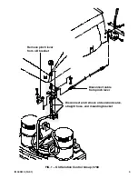
1. Disconnect and remove the front PVC hose from the solenoid valve and T--fitting mounted
to the top of the scrub head.
(Refer to FIG. 1)
2. Disconnect push/pull cable from the pinch lever on the valve mounting bracket.
3. Remove and set aside the pinch lever from the valve mounting bracket.
4. Remove and discard the straight hose connecting solution tank to solution control valve.
5. Remove and discard the old solenoid valve.
(Refer to FIG. 1)
6. Remove the old valve mounting bracket from the machine. Set the mounting hardware
aside.
(Refer to FIG. 1)

