background image

6

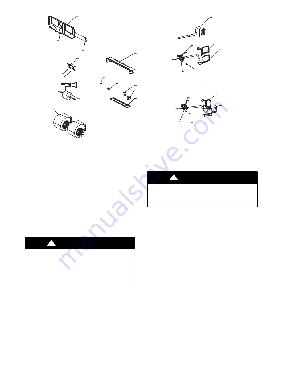
NOTE: This illustration is for reference only. Unit may differ in appearance or may not include all components shown.

6L]HV

6L]HV

([SDQVLRQ9DOYH$VVHPEO\

7;9

'LVWULEXWRU

25LQJ

'LVWULEXWRU

$VVHPE

l

\

+HDGHU$VVHPE

l

\

25LQJ

7;9

'LVWULEXWRU

'LVWULEXWRU
$VVHPE

l

\

([SDQVLRQ9DOYH$VVHPEO\

3ODWHHDWHU

7UDQVIRUPHU

3ODWH
+HDWHU%ODQN

*URXQG/XJ

7HUPLQDO%ORFN

)XVH

%ORZHU'HFN

&ODPS7XEH

%ORZHU0RWRU

0RWRU6XSSRUW

0RWRU6XSSRUW5LJKW

0RWRU6XSSRUW/HIW

%ORZHU+RXVLQJ:KHHO$VVHPEO\

0RXQW

,

0RWRU

A180051

Fig. 6 


FMU4Z and FMC4Z Models 

 Blower and Coil Parts

CARE AND MAINTENANCE

The minimum maintenance requirements for this equipment are as

follows:

1.

Inspect and clean or replace air filter each month or as re-

quired.

2.

Inspect cooling coil, drain pan, and condensate drain each

cooling season for cleanliness. Clean as necessary.

3.

Inspect blower motor and wheel for cleanliness each heating

and cooling season. Clean as necessary.

4.

Inspect electrical connections for tightness and controls for

proper operation each heating and cooling season. Service

as necessary.

CUT HAZARD

Failure to follow this caution may result in personal injury.
Sheet metal parts may have sharp edges or burrs. Use care and

wear appropriate protective clothing and gloves when handling

parts.

CAUTION

!

A. Air Filter

The air filter should be replaced as needed.

UNIT DAMAGE HAZARD

Failure to follow this caution may result in equipment damage.
Never operate unit without a filter.

CAUTION

!

B. Cooling Coil, Drain Pan, and Condensate Drain

The cooling coil is easily cleaned when it is dry. Inspect coil and

clean (if necessary) before each cooling season. To check or clean

cooling coil, remove blower/heater access panel to gain full access

to cooling coil. If coil is coated with dirt or lint, vacuum with a soft

brush attachment.
Be careful not to bend coil fins. If coil is coated with oil or grease,

clean it with a mild detergent and water solution. Rinse coil with

clear water.
Be careful not to splash water onto insulation.
Inspect drain pan and condensate drain at same time cooling coil is

checked. Clean drain pan and condensate drain by removing any

foreign matter from pan. Flush pan and drain tube with clear water.
If drain tube is restricted, it can generally be cleared by

high

pressure water. Cut plastic line and work outside condensate

pan and away from coil to clear drain tube.

NOTE

:  

There MUST be a trap in condensate line. Trap must be at

least 3

in. deep, not higher than the bottom of unit condensate

drain opening, and pitched downward to an open drain or sump.

Содержание FMC4X

Страница 1: ...of the Canadian Electrical Code CSA C22 1 Recognize safety information This is the safety alert symbol When you see this symbol on the unit and in instruction manuals be alert to the potential for personal injury Understand the signal words DANGER WARNING and CAUTION These words are used with the safety alert symbol DANGER identifies the most serious hazards which will result in severe personal in...

Страница 2: ...otor ELECTRIC HEATER SERVICE Service can be completed with heater in place Shut off power before servicing A Limit Switch Refer to Electric Heater Kit Function and Troubleshooting section of this manual B Relay Refer to Electric Heater Kit Function and Troubleshooting section of this manual C Transformer A 40 VA transformer supplies 24 V power for control circuit Check for 208 230V on primary side...

Страница 3: ...osed high voltage high current switch When system temperatures cool sufficiently the switch will automatically reset to its closed position Normal failure mode for this switch is open If a limit switch has been determined to be defective NEVER BYPASS THE LIMIT SWITCH When replacing limit switch ensure that it is replaced with a limit switch of identical opening temperature and closing differential...

Страница 4: ...ference only Unit may differ in appearance or may not include all components shown A180030 Fig 2 PSC Blower Parts NOTE This illustration is for reference only Unit may differ in appearance or may not include all components shown 1 Control Mounting Plate 3 Time Delay Relay 4 Blower Relay 5 Terminal Block 2 24v Transformer 6 Ground Lug 8 Motor Cover 7 Control Box Cover 9 Heater BlankOff Plate A18002...

Страница 5: ...ce or may not include all components shown A180028 Fig 4 Internal Case 4 Header Assy 1 Coil 2 pieces 2 Coil Support Plate Right Side 3 Coil Air Diverter 7 Capillary I 6 Capillary II 5 Distributor 9 Throttle 8 Coil Support Plate Left Side Piston Installed NOTE This illustration is for reference only Unit may differ in appearance or may not include all components shown A180029 Fig 5 Coil Parts ...

Страница 6: ...s Use care and wear appropriate protective clothing and gloves when handling parts CAUTION A Air Filter The air filter should be replaced as needed UNIT DAMAGE HAZARD Failure to follow this caution may result in equipment damage Never operate unit without a filter CAUTION B Cooling Coil Drain Pan and Condensate Drain The cooling coil is easily cleaned when it is dry Inspect coil and clean if neces...

Страница 7: ...move control box assembly five screws If there is not enough slack in field wiring high and low voltage it is recommended to disconnect field wiring A13386 Fig 8 Control Box Removal D FPM A B N FMC4X FMU4X Disconnecting the Blower Assembly 1 Disconnect power ELECTRICAL OPERATION HAZARD Failure to follow this warning could result in personal injury or death Before installation or servicing system a...

Страница 8: ... disconnected from the unit Be ready to lower the blower assembly CAUTION A13389 Fig 11 Remove Middle Screws E FPM A B N FMC4X FMU4X Servicing the Fan Motor 1 After removing the blower housing from the unit discon nect ground wire from screw on grounding bracket A13390 Fig 12 Disconnect Ground Wire 2 Remove grounding bracket from motor mount assembly At this point the clamp brackets will be loose ...

Страница 9: ...ting fluid inside is combustible and may ignite causing burns WARNING 4 Disconnect capacitor leads from capacitor A13393 Fig 15 Capacitor Leads 5 Loosen blower wheel set screws from each motor shaft ac cessing them through the blades of the blower wheels with a Phillips screwdriver A13394 Fig 16 Loosen Blower Set Screw 6 Disconnect one of the blower housings by removing the four housing screws A13...

Страница 10: ...move the two middle screws above behind the blower motor that s attached to the top plate 6 Remove the two outer screws that attach the blower support plate to right evaporator coil support See Fig 23 A180034 Fig 23 Remove Outer Screws from Support Plate 7 Remove the top and middle screw of the refrigerant tubing holding bracket See Fig 24 A180035 Fig 24 Remove Top and Middle Screw 8 Bend the hold...

Страница 11: ...y After removing the final screw from Step 9 the blower assembly will be completely disconnected from the unit Be ready to lower the blower assembly CAUTION G FMC4Z FMU4Z Servicing the Fan Motor 1 After removing the blower housing from the unit remove grounding bracket from motor mount assembly by remov ing the two screws See Fig 28 29 A180045 Fig 28 Screws Holding the Bracket A180046 Fig 29 Bend ...

Страница 12: ...ccessed for cleaning by removing either the control box assembly or the blower assembly Refer to those previous instructions I Removing the Drain Pan 1 Disconnect condensate drains if necessary 2 Remove the four screws located near the corners See Fig 33 3 Lower drain pan from unit A13398 Fig 33 Removing Condensate Pan J Changing the A Coil 1 Disconnect power 2 Disconnect field wiring low and high...

Страница 13: ...ide of the fan coil unit in line with the liquid refrigerant line FPMAN C U Fan coils are shipped with a piston metering device designed for the most common outdoor unit matches The piston included with the fan coil is unique to this product and cannot be replaced with the piston shipped with the outdoor unit Refer to AHRI ratings to check if your combination can use the piston shipped with the un...

Страница 14: ...P D 7310 W Morris St D Indianapolis IN 46231 Edition Date 03 18 Manufacturer reserves the right to change at any time specifications and designs without notice and without obligations Catalog No SM FPMA 03 Replaces SS FPMA 02 ...

Отзывы: