


F97CMN and G97CMN: Installation, Start-up, Operating and Service and Maintenance Instructions
Manufacturer reserves the right to change, at any time, specifications and designs without notice and without obligations.
23
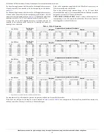
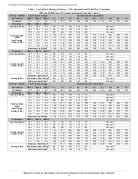
See Notes following table.
NOTES:
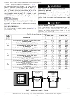
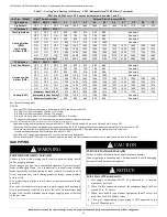
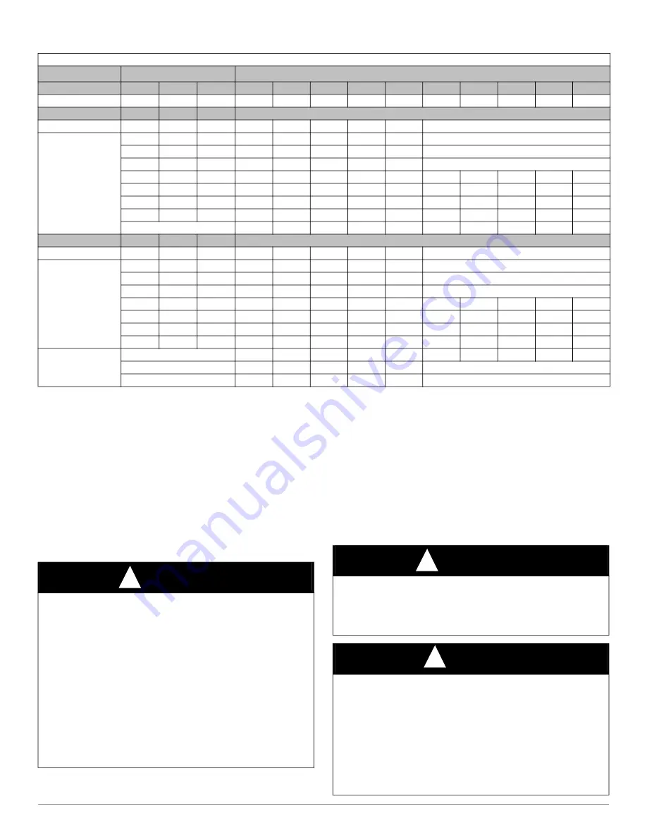
1.Nominal 350 CFM/ton cooling airflow is delivered with SW1-5 and SW4-3 set to OFF.
Set SW1-5 to ON for nominal 400 CFM/ton (+15% airflow).
Set SW4-3 to ON for nominal 325 CFM/ton (-7% airflow).
Set both SW1-5 and SW4-3 to ON for nominal 370 CFM/ton (+7% airflow).
This applies to Cooling and Low-Cooling airflow, but does not affect continuous fan airflow.
The above adjustments in airflow are subject to motor horsepower range/capacity.
2.
Maximum cooling airflow is achieved when switches SW2-1, SW2-2, SW2-3 and SW1-5 are set to ON, and SW4-3 is set to OFF.
3.
All heating CFM’s are when low/medium heat rise adjustment switch (SW1-3) and comfort/efficiency adjustment switch (SW1-4) are both set to OFF.
4.
Ductwork must be sized for high-heating CFM within the operational range of ESP. Operation within the blank areas of the chart is not
recommended because high-heat operation will be above 1.0 ESP.
5.
All airflow on 21” casing size furnaces are 5% less on side return only installations.
6.
Return air above 1800 CFM on 24.5” casing sizes requires two sides, one side and bottom or bottom only, to allow sufficient airflow to the furnace.
GAS PIPING
(SW1-5 and SW4-3 set to OFF, except as indicated. See notes 1 and 2.)
Unit Size: 1202422
Clg/CF Switch settings
External Static Pressure (ESP)
Clg Switches
SW2-3 SW2-2 SW2-1
0.1
0.2
0.3
0.4
0.5
0.6
0.7
0.8
0.9
1.0
Clg Default:
OFF
OFF
OFF
1850
1855
1860
1855
1850
1830
1805
1775
1750
1730
CF Switches
SW3-3 SW3-2 SW3-1
Low-Clg Default:
OFF
OFF
OFF
930
925
915
900
885
See note 4
Cooling Airflow
(SW2)
Low-Cooling
Airflow (SW3)
OFF
OFF
ON
765
745
740
705
680
See note 4
OFF
ON
OFF
930
925
915
900
885
See note 4
OFF
ON
ON
1095
1100
1110
1105
1085
See note 4
ON
OFF
OFF
1265
1255
1265
1280
1275
1285
1270
1260
1250
1230
ON
OFF
ON
1465
1455
1470
1465
1465
1470
1455
1450
1435
1415
ON
ON
OFF
1850
1855
1860
1855
1850
1830
1805
1775
1750
1730
ON
ON
ON
2200
2200
2200
2190
2185
2170
2145
2085
1990
1890
Maximum Clg Airflow
2
2200
2200
2200
2190
2185
2170
2145
2085
1990
1890
CF Switches
SW3-3 SW3-2 SW3-1
Cont. Fan Default:
OFF
OFF
OFF
930
925
915
900
885
See note 4
Continuous Fan
Airflow (SW3)
OFF
OFF
ON
765
745
740
705
680
See note 4
OFF
ON
OFF
930
925
915
900
885
See note 4
OFF
ON
ON
1095
1100
1110
1105
1085
See note 4
ON
OFF
OFF
1265
1255
1265
1280
1275
1285
1270
1260
1250
1230
ON
OFF
ON
1465
1455
1470
1465
1465
1470
1455
1450
1435
1415
ON
ON
OFF
1465
1455
1470
1465
1465
1470
1455
1450
1435
1415
ON
ON
ON
1465
1455
1470
1465
1465
1470
1455
1450
1435
1415
Heating (SW1)
Maximum Heat Airflow
3
1815
1820
1825
1820
1815
1795
1775
1745
1720
1700
Intermediate Heat Airflow
3
1095
1100
1110
1105
1085
See note 4
Minimum Heat Airflow
3
905
900
890
875
855
See note 4
Table 7 – Cooling
4
and Heating Air Delivery - CFM (Bottom Return
5
With Filter) (Continued)
WARNING
!
FIRE OR EXPLOSION HAZARD
Failure to follow this warning could result in personal injury, death,
and/or property damage.
Never purge a gas line into a combustion chamber. Never test for gas
leaks with an open flame. Use a commercially available soap solution
made specifically for the detection of leaks to check all connections. A
fire or explosion may result causing property damage, personal injury
or loss of life.
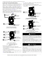
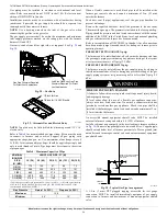
Use proper length of pipe to avoid stress on gas control manifold and
gas valve.
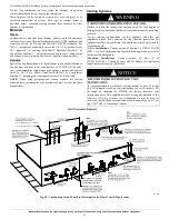
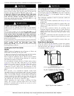
Gas valve inlet and/or inlet pipe must remain capped until gas supply
line is permanently installed to protect the valve from moisture and
debris. Also, install a sediment trap in the gas supply piping at the inlet
to the gas valve.
CAUTION
!
FURNACE DAMAGE HAZARD
Failure to follow this caution may result in furnace damage.
Connect gas pipe to furnace using a backup wrench to avoid damaging
gas controls and burner misalignment.
NOTICE
!
In the State of Massachusetts:
1. Gas supply connections MUST be performed by a licensed
plumber or gas fitter.
2. When flexible connectors are used, the maximum length shall not
exceed 36 in. (915 mm).
3. When lever handle type manual equipment shutoff valves are
used, they shall be T-handle valves.
4. The use of copper tubing for gas piping is NOT approved by the
State of Massachusetts.


