Instructions for use and maintenance
Electric motors 50-400 V CA
Page
13
of
22
8.7
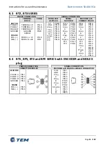
BTS, BPS, BTE and BPE SERIES with HALL SENSOR and MIL
CONNECTOR or CABLE OUTPUT
POWER CONNECTION
SIGNAL CONNECTION
MIL CONNECTOR
CABLE OUTPUT
HALL SENSOR
MOTOR
PHASE U
PHASE V
PHASE W
GROUND
BRAKE
POS.( + )
NEG.( - )
PTC (option)
PTC
PTC
PIN M
PIN J
PIN K
PIN L
PIN F
PIN C
PIN A
PIN B
RED
WHITE
BLACK
YELLOW/GREEN
WHITE
WHITE
BLUE
BLUE
MIL
CONNECTOR
CABLE
OUTPUT
+12Vcc
GND
Screen
PTC (option)
PTC (option)
PROBE W
PROBE V
PROBE U
PIN A
PIN B
PIN S
PIN J
PIN K
PIN P
PIN M
PIN V
BROWN
WHITE
BLACK (opt)
BLUE
BLUE
GREY
GREEN
YELLOW
NB: All motor are equipped with clamp or screw for grounding highlighted by the
symbol:
NB: The direction of rotation of the motor is the conventional one (clockwise rotation seen
power side) according to EN 60034-8
WARNING:
-
Verify that the drivers used have the CE mark or equivalent.
-
Ensure that connections to electrical sockets are protected from
flooding and moisture.
-
For motor connections and accessories use cables of appropriate
size, with shielding and ground conductor.
-
Failure to comply with the requirements may cause significant damage to the
motor.


