TELOS 2101 USER’S MANUAL
PART IV
THE STUDIO INTERFACE & ADDITIONAL HYBRIDS
IV-34
SECTION 1 – STUDIO INTERFACE INSTALLATION
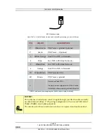
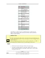
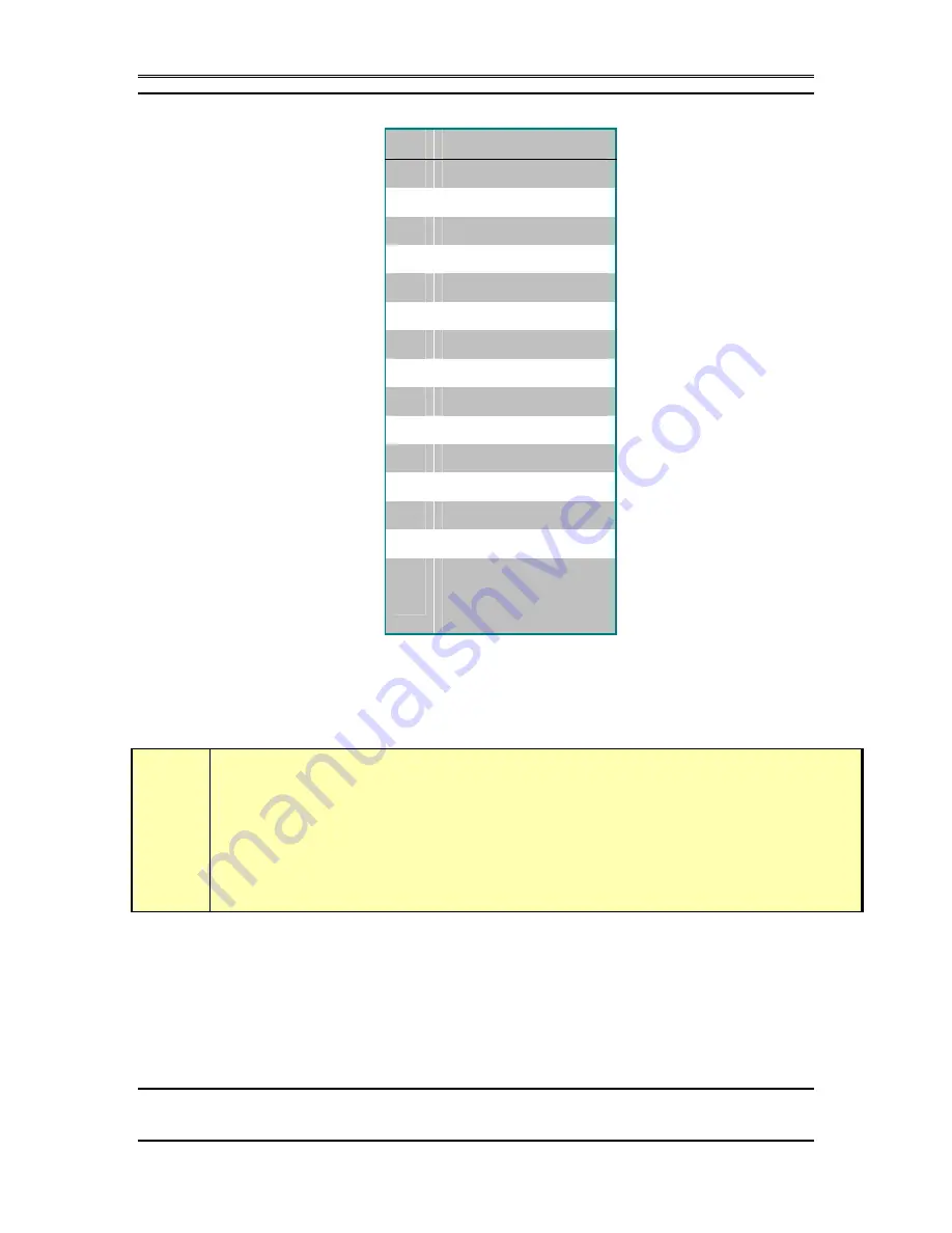
PIN FUNCTION
1
Ground
2
Priority Ringing Out
3
Record Start Out
4 Record
Stop
Out
5
N/C
6 <Reserved>
7
Ring Mute In
8*
+5 VDC (400 mA max)
9
N/C
10
User Out (Dump)
11
Ringing Out
12 N/C
13
<Reserved>
14 <Reserved>
15
N/C
*
This power pin is in parallel
with pin 3 of the SAA ports
Note that the +5 volts DC on pin 8 is in parallel with pin 3 on both SAA ports.
Failure to limit combined current on these pins to 400mA could cause hardware
damage or system instability.
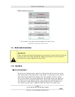
?
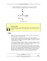
CURIOSITY NOTE!
The DB- designation for D- Sub connectors is from Cinch Corp’s part numbering system.
The proper Cinch designation for a 15 pin D- Sub connector is a DA- 15p (plug) or DA- 15s
(socket) not DB- 15!
Other Cinch designations for D- Sub connectors are; DE- 9, DB- 25, DC- 37 and DD- 50.
Our thanks going out to Mike Schweizer, for contributing this information.
Inputs
•
The function for each of the inputs is shown on the previous page.
•
All inputs are specially treated to accept either a voltage (up to 24 VDC), or a
closure to ground, which may be provided by switches, relays, or logic outputs.
The inputs are active low.

