TELOS 2101 USER’S MANUAL
PART IV
THE STUDIO INTERFACE & ADDITIONAL HYBRIDS
IV-13
SECTION 1 – STUDIO INTERFACE INSTALLATION
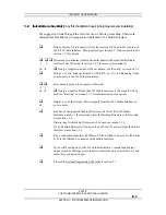
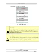
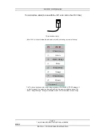
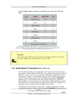
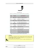
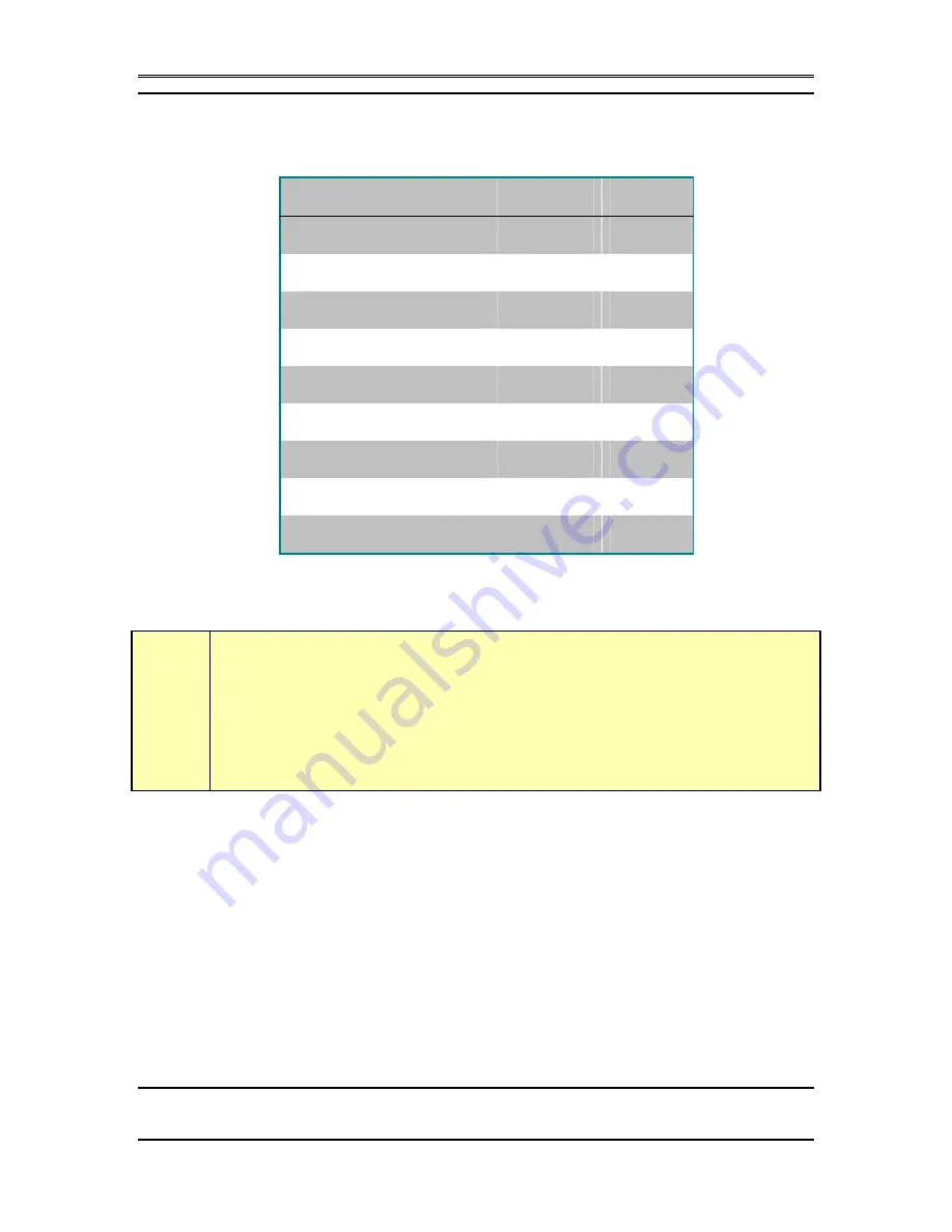
T-Link interface crossover cable (for use with Rev A T-Link card in the 2101
Hub)
PIN
COLOR
DIRECTION
PIN
1
White/Green
Å
4
2 Green
Å
5
3*
White/Orange
3*
4 Blue
Æ
1
5
White/Blue
Æ
2
6* Orange
6*
7*
White/Brown
7*
8* Brown
8*
*
Not used on the T- Link Interface
T-Link cable wiring diagram. Note that this is a special cable and both ends are not wired
identically. Note that the T-Link interface does not require all 8 conductors. This “crossover cable”
is for use only when Rev A T-Link cards are used in the 2101 Hub.
h
HOT TIP!
This cable must be fabricated on site and is not included with the Series 2101. Note
that this is
not
the same as an Ethernet “Crossover” cable.
1.3.2
Desktop Director™ Connections
(Studio Interface only)
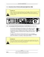
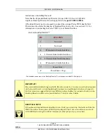
The 2101 Studio Interface has 2 Desktop Director™ ports located in slots F. Each
port supports 1 Desktop Director™ directly. The internal power supply of the Studio
Interface can power up to two (2) 12 line Desktop Directors without the need of an
external power supply. A second Desktop Director can be added to each port (for a
total of 4) using a Desktop Director Power Supply Kit (Telos part # 2001-00024)
available from your Telos Dealer. Each Power Supply kit allows one additional
Desktop Director. An expander kit is also required for any Desktop Director located
more than 250 feet (75 meters) from the Studio Interface. One Power Supply Kit is
required for each two Desktop Directors added in excess of two.
An additional two Desktop Director ports may be added by installing an optional
second Desktop Director Interface card (Telos part # 2001-00022). See section 4 for


