S50 Hardware User Guide
1VV0301505 Rev. 3
Page 24 of 60
2021-05-05
Not Subject to NDA
4.10.
Slow Clock Interface
Even though an external slow clock is not required for BLE operation, consumption of
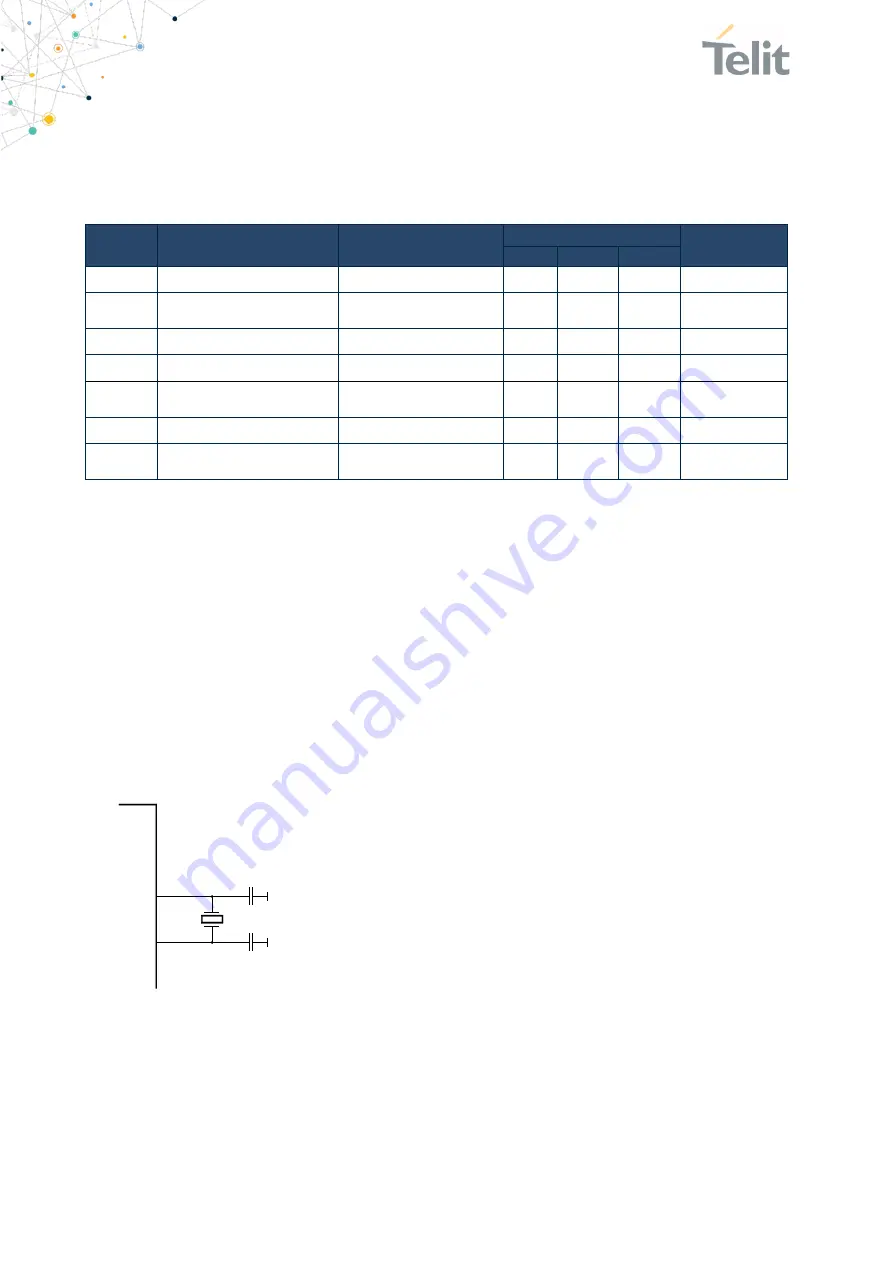
power during power-down modes can be reduced by connecting an XTAL (32,768kHz) and
two capacitors C1, C2 at pins XL-IN and XL-OUT.
Symbol
Item
Condition
Limit
Unit
Min
Typ
Max
f
NOM
Crystal Frequency
T
amb
= 25°C
32,768
kHz
f
TOL
Frequency Tolerance for
BLE applications
including temperature
and aging
(1)
+/-250
ppm
C
L
Load Capacitance
12,5
pF
C0
Shunt Capacitance
2
pF
R
S
Equivalent Series
Resistance
100
k
Ω
P
D
Drive Level
1
µW
C
pin
Input Cap. On XL-IN and
XL-OUT
4
pF
(1)
adjust crystal frequency by choosing correct value for C1, C2 (value depends on CL of crystal and layout)
Table 5: 32,768kHz Crystal Oscillator
The module’s firmware will detect the presence of a slow clock during the boot process
and switch behavior appropriately.
4.10.1.
Connection of an External 32,768 kHz Crystal
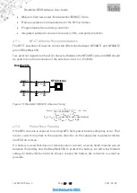
Connect the 32,768 kHz crystal and two capacitors C1, C2 at pins A-6 (XL-IN) and A-5 (XL-
OUT). The exact value of C1 and C2 depends on the crystal and the stray capacitance of
the layout. Select C1, C2 such that the slow clock oscillator operates at the exact
frequency at room temperature (25°C). C1 and C2 shall be of equal capacity. The crystal
and the capacitors shall be located as close as possible to pins A-5, A-6.
CL = (C1+Cpin+Cs) * (C2+Cpin+Cs) / (C1+C2+2*Cpin+2*Cs), or
C1, C2 = (2*CL
–
Cpin
–
Cs)
Cpin: see Table 5
Cs: stray capacitance, depends on layout
Figure 14: S50 connection of external XTAL
XL-IN
S50
A-6
Slow Clock
XL-OUT
A-5
32,768kHz
CL: 9pF
C1
C2
C1, C2 ~ 12pF
Содержание BlueMod+S50
Страница 1: ...BlueMod S50 HW User Guide 1VV0301505 Rev 3 2021 05 05 Telit Technical Documentation...
Страница 60: ......

