


LE910Cx HW User Guide
1VV0301298 Rev. 33
Page 69 of 128
2021-06-29
Not Subject to NDA
Serial Ports
The serial port is typically a secondary interface between the LE910Cx module and OEM
hardware. The following serial ports are available on the module:
•
Modem Serial Port 1 (Main)
•
Modem Serial Port 2 (Auxiliary)
Several serial port configurations can be designed for the OEM hardware. The most
common are:
•
RS232 PC com port
•
Microcontroller UART @ 1.8V (Universal Asynchronous Receive Transmit)
•
Microcontroller UART @ 3.3V/5V or other voltages different from 1.8V
Depending on the type of serial port on the OEM hardware, level translator circuits may
be required to operate the system. The only configuration that does not need level
translation is the 1.8V UART.
The LE910Cx UART has CMOS levels as described in Section 4.3, Logic Level
Specifications.
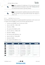
8.4.1.
Modem Serial Port 1 Signals
On the LE910Cx, Serial Port 1 is a +1.8V UART with 7 RS232 signals. It differs from the
PC-RS232 in the signal polarity (RS232 is reversed) and levels. Table 28 lists the signals
of LE910Cx Serial Port 1.
RS232 Pin#
Signal
Pad No.
Name
Usage
1
DCD - DCD_UART
N14
Data Carrier Detect
Output from
LE910Cx that
indicates carrier
presence
2
RXD - TX_UART
M15
Transmit line *see
Note
Output transmit line
of LE910Cx UART
3
TXD -RX_UART
N15
Receive line *see
Note
Input receive line of
LE910Cx UART
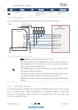
Note:
ETH_INT_N is a 1.8V input. It has an internal pull up to 1.8V
inside the module thus it should be connected to an open drain
interrupt pin of the Ethernet PHY. In case the PHY does not support
1.8V I/O, proper level shifter needs to be used.


