background image

12

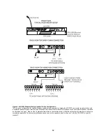
Figure 4 - MS-2002 Binaural Master Speaker Station Configuration.

This is a good configuration for smaller intercom systems when you want to operate the MS-2002 as a master speaker station, with
a separate speaker for each intercom channel. Make sure the MS-2002 internal DIP switches are set for binaural speaker operation
as described on page 7. Also, set the Combine/Isolate switch to the Isolate position. With this setting the two intercom channesl are
completely separated. The internal amplified speaker is used as the speaker output for channel 1, and the SPK-2000 is used for
channel 2.

Содержание MS-2002

Страница 1: ...1 User Instructions Model MS 2002 Master Station and Power Supply 9350 7749 000 Rev B 10 2003 Audiocom Intercom Systems ...

Страница 2: ...o Audiocom products It is the responsibility of the user to determine before purchase that this product is suitable for the user s intended purpose ANY AND ALL IMPLIED WARRANTIES INCLUDING THE IMPLIED WARRANTY OF MERCHANTABILITY ARE LIMITED TO THE DURATION OF THIS EXPRESS LIMITED WAR RANTY NEITHER TELEX NOR THE DEALER WHO SELLS TELEX PRODUCTS IS LIABLE FOR INCIDENTAL OR CONSEQUEN TIAL DAMAGES OF A...

Страница 3: ...ral or Binaural Operation DIP Switches 8 Balanced Unbalanced Switches 9 Direct Program Listen Enable Disable Jumpers 9 Mounting 9 Connections 9 External Program Input and PA Output 9 Cables 10 Power Up Check 16 Test Tone 16 Sidetone Adjustment 16 Voice Activated Microphone Vox Setup 17 Operation 17 Public Address PA 19 Using Mic Kill 19 Using Voice Activated Microphone Vox 19 Incoming Call Beep On...

Страница 4: ...r unbalanced dynamic microphone 2 PANEL MIC ELECTRET MIC HEADSET CONNECTOR Accepts an electret gooseneck microphone such as the Telex Model MCP 90 XX The model MCP 90 series panel mic connector is a 1 4 stereo plug with a threaded shaft for easy installation 3 VOLUME CONTROL Adjusts headphone volume only 4 VOX TRIMMERS Used with the voice activated microphone feature Separate trimmers adjust the v...

Страница 5: ...L AC POWER INPUT The MS 2002 accepts any input power in the range of 100 240 VAC 50 60 Hz 16 2 CHANNEL INTERCOM CABLE CONNECTORS One male and one female XLR 6 connector for 2 channel operation with SS2002 BP2002 etc 17 PROGRAM INPUTS CONNECTOR AND TRIMMERS Each intercom channel has its own program input and level adjust trimmer The program inputs may be turned on or off via the front panel and the...

Страница 6: ... a y t n a r r a W 1 l a u n a M r e s U 2 s e t a l P e c a F k c a l B WARNING The following instructions are for use by qualified personnel only To avoid electric shock do not remove the cover unless you are qualified to do so AVERTISSEMENT Les instructions qui suivent s adressent uniquement a un technicien qualifie Pour evite des chocs electriques ne pas ouvrir le boitier a moins d y entre hab...

Страница 7: ...BALANCED L A B UNBALANCED L A B N U OPERATION BOTH SWITCHES MUST BE SET THE SAME FACTORY DEFAULT IS BALANCED l e n a P r a e R m o C r a e l C r o m o c o i d u A n o i t a r e p o m o c o i d u A d e c n a l a B t u O m o C r a e l C d e c n a l a b n U n I L A B t u O l e n a P r a e R m o C r a e l C r o m o c o i d u A n o i t a r e p o m o c o i d u A d e c n a l a B t u O m o C r a e l C d e...

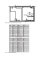
Страница 8: ...alk set SW1 7 to on 2 For channel 2 program interrupt during talk set SW1 8 to on Incoming Call Beep DIP Switches If call signal receive is enabled switches SW1 3 and SW1 5 incoming calls will be indicated by red flashing Call keys An optional beep tone can also be used Internal switches enable the beep tone You can then turn the beep tone on or off via the front panel during normal operation Enab...

Страница 9: ...d black face plates on the appropriate side The face plates should be mounted with the groves on the top Note You will have to perform the sidetone adjustment page after all components are connected With the MS 2002 being rack mounted you may not be able to access the sidetone trimmers In this case you can position the MS 2002 in the rack and make all required connections Then adjust the sidetone ...

Страница 10: ... and SPK 2000 5 18 457 mm EXP IN OUT cable stereo miniplug to stereo miniplug One supplied with each EMS4001 6 18 457 mm CHANNEL OUTPUT cable 15 pin Male Dsub to 15 pin Male Dsub One supplied with each EMS4001 Optional component See EMS4001 User Manual for connection information 7 Shielded patch cable 9 pin Male Dsub to 9 pin Female Dsub Customer local purchase available at Radio Shack etc Note Al...

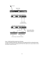
Страница 11: ... the MS 2002 as a master speaker station with one speaker to monitor both intercom channels In this configuration the Combine Isolate switch is set to the Isolate position With this setting the 2 intercom channels are completely separated The MS 2002 dip switches are set to monaural operation so that both intercom channels are heard in the speaker ...

Страница 12: ... a separate speaker for each intercom channel Make sure the MS 2002 internal DIP switches are set for binaural speaker operation as described on page 7 Also set the Combine Isolate switch to the Isolate position With this setting the two intercom channesl are completely separated The internal amplified speaker is used as the speaker output for channel 1 and the SPK 2000 is used for channel 2 ...

Страница 13: ...al headphones binaural headphone operation is not supported Note that belt packs use less power than speaker stations and you can daisy chain more of them on a signle cable run Avoid very long cable runs with daisy chained speaker stations This example shows how you would home run an SS2002 speaker station when the cable is very long Also set the Combine Isolate switch to the Isolate position With...

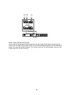
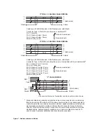
Страница 14: ... a user supplied DB9M connector Refer to the program input connector specifications located on page 20 for connector pin out However a more convenient method is to use an XP USPG Breakout Panel as shown The XP USPG also interfaces the PA jack of the MS 2002 to a standard 2 pin XLR audio cable Note The XP USPG Breakout Panel can be rack mounted using a BOP 1000 Rack Mount Plate ...

Страница 15: ...in 1 Common Pin 2 Shield Standard cables are generally constructed using a male connector at one end and a female connector at the other end This allows several cables to be interconnected to create longer cable runs Audiocom power supplies use a 3 pin male Neutrik connector for each channel Audiocom wallplates use male Neutrik connectors Audiocom master stations speaker stations and belt packs al...

Страница 16: ...r returned voice audio and re amplify it This could also happen if you are using a headset where the ear cushions do not completely cover the ears although it is probably much less likely In either of these cases you should minimize the amount of sidetone On the other hand if you are using headphones that completely enclose the ears a certain amount of your own voice level is desirable to overcome...

Страница 17: ... direction until the Panel Mic key just returns to steady orange mic off If you are wearing a headset make sure that breathing and movement do not cause the Panel Mic key to flicker green If they do adjust the Vox control slightly more in the counterclockwise direction to eliminate this 5 Speak into the microphone in a normal voice and check that the headset key immediately turns green when you ta...

Страница 18: ... hold the Call key for the channel that you want to call An inaudible call signal will be sent and your listen key for that channel will automatically turn on in preparation to receive a verbal response 2 When you hear a response release the Call key 3 If you are using manual microphone activation instead of Vox make sure your microphone is on for a dynamic mic headset tap the Headset key to turn ...

Страница 19: ... or on all channels This feature is useful when a remote talk key has been left on and is causing unwanted noise on a channel Use Mic Kill as follows 1 Tap the Mic Kill key It will blink green 2 Tap the Talk or Listen key for a channel to turn off all talk keys on that channel Or tap the All Talk key to turn off all talk keys The key you tap will turn green and the Mic Kill signal will be sent 3 T...

Страница 20: ...ones 150 to 600 ohm monaural Connector Type XLR 4M Pin 1 Microphone low Pin 2 Microphone high Pin 3 Headphone high Pin 4 Headphone low Panel Microphone Input Microphone Type Electret condenser Power Phantom 5 VDC Nominal Level 42 dBu Maximum Level 25 dBu Connector Type IKP12 MCP 90 series stereo plug connector Program Input Input Level 100mV maximum Voltage Gain 25 3 dB Output Level to intercom ch...

Страница 21: ...ed Configuration Pinouts Pin 1 Common Pin 2 Intercom audio low and 24 VDC input Pin 3 Intercom audio high and 24 VDC input XLR 6 Balanced Configuration Pinouts Pin 1 Audio and DC Common Pin 2 Local power 12 to 15 VDC 65 to 150 mA Pin 3 Intercom channel 1 audio low and 24 VDC phantom power Pin 4 Intercom channel 1 audio high and 24 VDC phantom power Pin 5 Intercom channel 2 audio low and 24 VDC pha...

Страница 22: ... Phone Jack Tip PA output high Ring Not used Sleeve Common Speaker Output Output Level 0 dB nominal 1 0 Vrms Output Impedance 1000 ohms nominal Frequency Response 200 Hz to 8 kHz 1 3dB Connector Type RCA Phono Jack Tip Speaker output high Sleeve Common Expansion Input Output Type 2 0 mm stereo phone jack Tip Talk output Ring Listen input Sleeve Common Headphone Amplifier Voltage Gain 30 3 dB Maxim...

Страница 23: ...e r a s y e k n e t s i L d n a k l a T e h t d n a n e e r g t i x e o t s l e n n a h c l l a l l i k c i M n e e r g k n i l b l l i w y e k l l i K c i M k l a T l l A p a t n e h t l l i K c i M p a T t i x e o t l l i K c i M p a T n e e r g e r a s y e k n e t s i L d n a k l a T l l a d n a n o m a r g o r P p a T n e e r g s i y e k y e k k l a T s l e n n a h c p a t n e h t l l i K c i ...

Страница 24: ......

Отзывы: