42 Maintenance
Airman 8
3.1.5.1 Speaker Sensitivity and Frequency Response Verification
NOTE:
The Airman 8 headset was designed, tested, and approved to FAA TSO C139a.
The TSO requires the headset meet the minimum performance specifications as
defined in RTCA DO-214a. This document and specifications listed here reference
the test procedures and equipment used as defined in these standards. Refer to the
standard for details on how to perform individual tests.
All models tested, unless noted otherwise.
Transducer type:
Dynamic
Transducer:
600
Impedance (at the earphone plug):
Must meet standards outlined in the
specifications table in either the technical
manual or the technical data sheet.
Sensitivity:
Frequency Response:
3.1.5.2 Measure the Resistance (Plug to PCBA)
To
measure the resistance
, do the following:
Using an Ohm Meter, place one probe on
J5
and the other probe on
J6
or
J17
.
If measured 300
Ω ±20%
, continuity is good.
If measured at 600
Ω
, one of the speaker paths is defective.
If measured at 270
Ω
or less, there is a short in the speaker path.
3.1.5.3 Validate the Boom Side PCBA
To
validate the boom side PCBA
, do the following:
1. On the boom side PCBA, send a
1kHz sine wave, 1Vrms signal from J5 to J6
.
2. Verify the
ANR switch is in the OFF position
.
3. Using an oscilloscope, place one probe at
J13
and place the other probe at
J14
.
If a signal is found, the board is good and if no sound is heard from the speaker, the
speaker or wiring is bad. Determine if the speaker needs to be replaced or the wires
need re-soldering.
If a signal is not found, the board is not good and should be replaced.
3.1.5.4 Validate the Non-boom Side PCBA
To
validate the non-boom side PCBA
, do the following:
1. On the boom side PCBA, send a
1kHz sine wave, 1Vrms signal from J5 to J6
.
2. Verify the
ANR switch is in the OFF position
.
3. On the non-boom side board using an oscilloscope, place one probe at
J13
and place
the other probe at
J14
.
If a signal is found, the board is good and if no sound is heard from the speaker, the
speaker or wiring is bad. Determine if the speaker needs to be replaced or the wires
need re-soldering.
If a signal is not found, the board is not good and should be replaced.
Содержание Airman 8
Страница 33: ...Airman 8 Parts List and Disassembly Assembly 33 5 Firmly press the headband pad into place...
Страница 34: ...34 Parts List and Disassembly Assembly Airman 8...
Страница 36: ...36 Maintenance Airman 8...
Страница 38: ...38 Maintenance Airman 8...
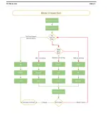
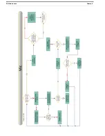
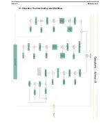
Страница 41: ...Airman 8 Maintenance 41 3 1 5 Speaker Troubleshooting and Workflow...
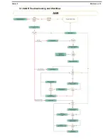
Страница 43: ...Airman 8 Maintenance 43 3 1 6 ANR Troubleshooting and Workflow...
Страница 47: ...Airman 8 Maintenance 47 3 Coil the cord into a loop 4 Place the coiled cord and headset in the carrying case...
Страница 48: ...48 Maintenance Airman 8...
Страница 52: ...Bosch Security Systems Inc 12000 Portland Avenue South Burnsville MN 55337 U S A www boschcommunications com...

