08354B DCN7877
Teledyne API T640 PM Mass Monitor
28
6.
For the T640:
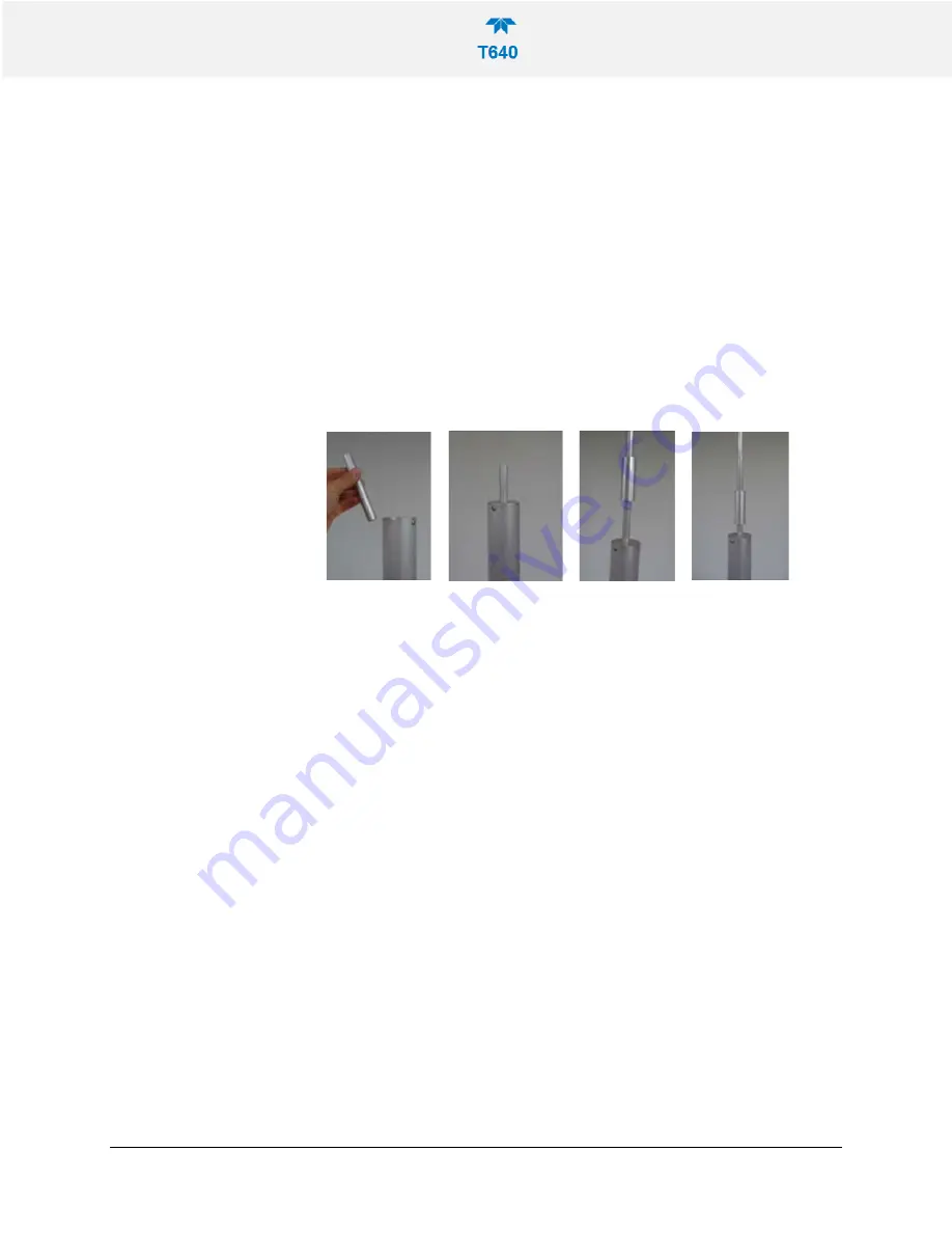
a. At the top of the ASC, insert the ~6” 5/8”OD Upper Inlet Tube into the
end of the ASC.
•
The Upper Inlet Tube should slide into the top of the ASC (about 2”)
and bottom out when completely inserted.
b. Place the Slip Coupler on top of the Upper Inlet Tube until the tube is
midway through the Slip Coupler.
c. Slide the 8’ sample line extension down through the tripod and the roof
penetration until it meets the opening of the Slip Coupler. Slide the
extension tube down into the Slip Coupler until it meets the Upper Inlet
Tube so that the 5/8” tubes are flush within the Slip Coupler.
d. Position the slip coupler so that the tubing is joined and centered over
where the seam between the two tubes meet.
The following pictures demonstrate the steps of the installation:
Figure 2-16. T640 Inlet Tube and Slip Coupler Assembly
7.
For the 640x:
a. At the top of the ASC, insert the 11” long (5/8” OD) upper inlet tube into
the ASC. Make sure to install with the tapered end facing up.
•
The upper inlet tube should slide into the top of the ASC (about 2”) and
bottom out when completely inserted.
b. Place the 12” long, 1.25” OD extension tube over the upper inlet tube
and seat onto the bypass flow coupler that is on the top of the ASC
c. Place the 1.25” to 1” fitting on top of the 12” long extension tube (this
coupler allows for usage of the 1” tube Slip Coupler)
d. Slide the 1” OD sample line extension down through the tripod and the
roof penetration until it meets the opening of the Slip Coupler. Slide the
extension tube down into the Slip Coupler until it bottoms out on the
tubing adapter.
e. With the Slip Coupler all the way down, the seam between the extension
tube and the adapter is in the middle of the Slip Coupler.
The following pictures demonstrate the steps of the installation:


