background image

October 2017 

RiverPro and RioPro ADCP Guide 

Page 160 

EAR-Controlled Technology Subject to Restrictions Contained on the Cover Page.


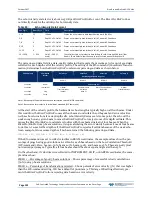
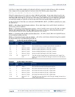
Table 28: 

Surface Layer Velocity Data Format 

Hex Digit 

Binary Byte  Field 

Description 

1-4 

1,2 

Velocity ID 

Stores the surface layer velocity data identification word (10 01h). 

5-8 

3,4 

Depth Cell 1, Veloc-

ity 1 

Stores velocity data for depth cell #1, velocity 1.  

9-12 

5,6 

Depth Cell 1, Veloc-

ity 2 

Stores velocity data for depth cell #1, velocity 2.  

13-16 

7,8 

Depth Cell 1, Veloc-

ity 3 

Stores velocity data for depth cell #1, velocity 3.  

17-20 

9,10 

Depth Cell 1, Veloc-

ity 4 

Stores velocity data for depth cell #1, velocity 4.  

21-84 

11-42 

Cells 2 – 5  
(if used) 

These fields store the surface layer velocity data for depth cells 2 through 5 (depend-

ing on measurement conditions). These fields follow the same format as listed above 

for depth cell 1. 


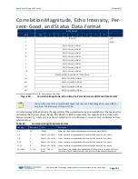
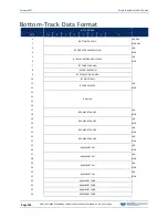
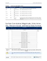
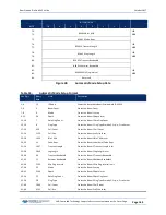
Surface Correlation Magnitude, Echo Inten-

sity, Percent-Good, and Status Data Format 


BIT POSITIONS 


BYTE 

7/S 


ID CODE 

LSB  


MSB  

DEPTH CELL #1, FIELD #1 


DEPTH CELL #1, FIELD #2 


DEPTH CELL #1, FIELD #3 


DEPTH CELL #1, FIELD #4 


DEPTH CELL #2, FIELD #1 


DEPTH CELL #2, FIELD #2 


DEPTH CELL #2, FIELD #3 


10 

DEPTH CELL #2, FIELD #4 


(SEQUENCE CONTINUES FOR UP TO 5 CELLS 


19 

DEPTH CELL #5, FIELD #1 


20 

DEPTH CELL #5, FIELD #2 


21 

DEPTH CELL #5, FIELD #3 


22 

DEPTH CELL #5, FIELD #4 


See Table 29 through Table 31 for a description of the fields. 

Figure 37. 

Surface Data Correlation Magnitude, Echo Intensity, Percent-Good, and Status Data 

Format 


The number of Surface Layer depth cells is specified by the Surface Layer Leader Cell Count 

field. 


Содержание RIOPRO

Страница 1: ...cense license exception or other approval from the appropriate U S Government agency before being exported from the United States or provided to any foreign person Diversion contrary to U S law is prohibited RIVERPRO RIOPRO ADCP GUIDE P N 95B 6097 00 October 2017 2017 Teledyne RD Instruments Inc All rights reserved ...

Страница 2: ...Page ii EAR Controlled Technology Subject to Restrictions Contained on the Cover Page ...

Страница 3: ...ling Guidelines 17 Assembly Guidelines 17 Deployment Guidelines 17 CHAPTER 2 INSTALLATION 19 Attaching the Boat Mounting Plate 20 Boat Assembly 21 Boat Battery Connection 22 I O Cable and Dummy Plug 23 Using the Cable Clips 24 Routing Cables 25 Cable Wiring Diagram 26 Mounting the Instrument 27 Over the Side Mounting 28 In Hull Mounting 29 CHAPTER 3 COLLECTING DATA 31 RiverPro RioPro Operation Ove...

Страница 4: ...Instrument Transformation Matrix 58 Pre deployment Test 59 Display Heading Pitch Roll and Voltage 59 CHAPTER 6 TROUBLESHOOTING 61 System Status and LED Behavior 62 Fuse Replacement 63 Boat Wiring Diagram 64 CHAPTER 7 RETURNING SYSTEMS TO TRDI FOR SERVICE 65 Shipping the RiverPro RioPro 66 Returning Systems to the TRDI Factory 67 Returning Systems to TRDI Europe Factory 68 CHAPTER 8 SPECIFICATIONS ...

Страница 5: ...0 EZ Sensor Source 103 Recorder Commands 104 Available Recorder Commands 104 Recorder Command Descriptions 104 ME Erase Recorder 104 MM Show Memory Usage 105 MN Set File Name 105 MR Set Recorder On Off 105 MQ Streaming Download 106 MY Y Modem output 106 Performance and Testing Commands 107 Available Performance and Testing Commands 107 Performance and Testing Command Descriptions 107 PA Run Go No ...

Страница 6: ... Beam Bin Size 133 ZV Vertical Beam Ambiguity Velocity 133 CHAPTER 10 OUTPUT DATA FORMAT 135 PD0 Output Data Format 136 Header Data Format 138 Fixed Leader Data Format 140 Variable Leader Data Format 145 Velocity Data Format 149 Correlation Magnitude Echo Intensity Percent Good and Status Data Format 151 Bottom Track Data Format 154 Surface Layer Velocity Leader Format 158 Surface Layer Velocity F...

Страница 7: ...4 Figure 22 96B 6060 RiverPro Outline Installation Drawing 75 Figure 23 967 6150 RioPro 1200 kHz Outline Installation Drawing 76 Figure 24 Installing Feature Upgrades 80 Figure 25 X Y and Z Velocities 101 Figure 26 RiverPro RioPro Coordinate Transformation 102 Figure 27 RiverPro RioPro Pitch and Roll 102 Figure 28 PD0 Standard Output Data Buffer Format 137 Figure 29 Header Data Format 138 Figure 3...

Страница 8: ...cho Intensity Data Format 152 Table 24 Percent Good Data Format 153 Table 25 Status Data Format 153 Table 26 Bottom Track Data Format 156 Table 27 Surface Layer Leader Format 158 Table 28 Surface Layer Velocity Data Format 160 Table 29 Surface Correlation Magnitude Data Format 161 Table 30 Surface Echo Intensity Data Format 161 Table 31 Surface Percent Good Data Format 162 Table 32 Surface Status ...

Страница 9: ...ro manual Updated the RiverPro RioPro Inventory Updated the LED behavior table Added the Boat Wiring Diagram Added Beam Coordinate Systems information to the EX command Updated the PT3 command Updated the GPS specifications Updated the outline installation drawings October 2014 Initial release EXCLUSIONS AND OMISSIONS This manual covers the RiverPro RioPro ADCP hardware and firmware For instructio...

Страница 10: ...aude France Phone 1 858 842 2600 Phone 33 0 492 110 930 FAX 1 858 842 2822 FAX 33 0 492 110 931 Sales rdisales teledyne com Sales rdie teledyne com Field Service rdifs teledyne com Field Service rdiefs teledyne com Client Services Administration rdicsadmin teledyne com Web http www teledynemarine com rdi For all your customer service needs including our emergency 24 7 technical support call 1 858 ...

Страница 11: ...de program names WinRiver II and file names default txt Code or sample files are printed using a fixed font Here is an example break RioPro Teledyne RD Instruments c 2015 All rights reserved Firmware Version 56 03 There are four visual aids to help This paragraph format indicates additional information that may help avoid problems or that should be considered in using the described features This p...

Страница 12: ...Page xii EAR Controlled Technology Subject to Restrictions Contained on the Cover Page NOTES ...

Страница 13: ... Subject to Restrictions Contained on the Cover Page Page 1 Chapter 1 AT A GLANCE In this chapter RiverPro RioPro Inventory RiverPro RioPro Options System Overview Computer Overview Power Overview Setting up the RiverPro RioPro ADCP Caring for the RiverPro RioPro System ...

Страница 14: ...Software CD Utility and testing software package including BBTalk that can be used to test the ADCP 907 8080 00 SxS Pro Software CD optional Section by Section SxS Pro is a stationary ADCP discharge data collection and pro cessing program This CD will be included with the SxS Pro upgrade registration code is required to collect data 91B 8007 00 90B 8020 00 CD Q View Software optional Q View is des...

Страница 15: ... sunlight Always apply lubricant before connecting the I O cable to the RiverPro The RiverPro is intended to be operated as a surface mounted system only No depth rating is provided The Thermistor measures the water temperature The black urethane faces covers the transducer ceramics The Vertical Beam allows for depth measurement directly under the RiverPro Never set the transducer on a hard surfac...

Страница 16: ...e I O connector should not be exposed to extended periods of heat or direct sunlight Always apply silicone lubricant before connecting the I O cable to the RioPro The RioPro is intended to be operated as a surface mounted system only No depth rating is provided The Thermistor measures the water temperature The orange urethane faces covers the transducer ceramics Never set the transducer on a hard ...

Страница 17: ...re 1 RiverRay RiverPro RioPro Boat Overview Computer Overview TRDI designed the RiverPro RioPro ADCP to use a Windows compatible computer The computer con trols the RiverPro RioPro and displays its data usually through our WinRiver II or SxS Pro programs Minimum Computer Hardware Requirements Windows 10 Windows 8 Windows 7 Desktop Laptop or Netbook computer Screen resolution above 1024x768 One Ser...

Страница 18: ...ofiling mode which automatically adjusts velocity profiling parameters every ensemble reading based on the water depth and other characteristics to maintain a balance between velocity precision spatial resolution and data storage requirements This ap proach allows consistent data quality throughout a transect and discharge measurement regardless of changes in the water depth or flow characteristic...

Страница 19: ...t cables sold separately Hemisphere A101 DGPS kit Hemisphere A101 Smart Antenna DGPS configuration cable Hemisphere Atlaslink DGPS kits Atlas capable Hemisphere Atlaslink Smart Antenna DGPS with configuration cable L1 L2 GLONASS and RTK support optionally available Hemisphere S321 DGPS kits Atlas capable Hemisphere S321 Smart Antenna DGPS with configu ration cable integrated batteries and integrat...

Страница 20: ...r Bluetooth code In all cases the code is 0 or 0000 zero not the letter o The pin code is 0 for systems shipped prior to August 2017 and 0000 for systems shipped after August 2017 If your system is sent in for repair and the Bluetooth module is replaced the pin code if needed will change from 0 to 0000 For RiverPro RioPro systems shipped after August 2017 the Microsoft Bluetooth drivers work with ...

Страница 21: ...ward The selection of Mode 0 or Mode 1 is independent of Authentication no Authentication Mode 1 automatically reconnects to the ADCP but is otherwise identical to Mode 0 You must establish an outgoing connection before you can switch to Mode 1 but once in Mode 1 you can connect to a different ADCP without switching back to Mode 0 4 Exit the ParaniWin program 5 Start WinRiver II 6 On the Configure...

Страница 22: ... Instruments c 2015 All rights reserved Firmware Version 56 xx 11 Click the Close button to exit the Test Port Dialog 12 Click the Close button once more to exit the Peripherals Configuration Dialog 13 Start a new measurement in WinRiver II 14 On the Configuration Dialog ensure the ADCP type matches the RiverPro RioPro and the indicator next to the RiverPro RioPro is green Verify the blue LED on t...

Страница 23: ... computer s communication port The standard communications set tings are RS 232 115200 baud no parity 8 data bits and 1 stop bit 3 Connect a battery or DC power supply to the power connectors Verify that both the red and green LEDs light After a few seconds the red LED should go out and the green LED will blink twice and then stay on This indicates that the RiverPro RioPro self test has passed Fig...

Страница 24: ...e the BBTalk desktop icon to start BBTalk Select the COM port the RiverPro RioPro ADCP cable is connected to Click Next BBTalk can be used with Bluetooth communica tions Right click on the RDI RPro icon in the Bluetooth management software and make sure that that it is connected and verify what COM Port is used Enter the Baud Rate Parity Stop Bits and Flow Con trol If you are unsure of the setting...

Страница 25: ...or B on the Toolbar The banner message should appear on the log file win dow The BBTalk toolbar will display if it is config ured for using Software Breaks or B if it is configured to send a Hard Break If the RiverPro RioPro ADCP does not respond check the serial port cables DC power supply or bat tery connection If necessary refer to the Trouble shooting section If the banner is not readable or v...

Страница 26: ...he End key At the prompt in the communication window type CR1 then press the Enter key This will set the RiverPro RioPro to the factory default settings BAUD RATE CB command 1200 CB111 2400 CB211 4800 CB311 9600 CB411 19200 CB511 38400 CB611 57600 CB711 115200 CB811 Default Send the CB command that selects the baud rate you wish The table on the left shows the CB command set tings for different ba...

Страница 27: ... Guide for details on using BBTalk Enabling the Loop Recorder The loop recorder is off by default To enable the loop recorder 1 Start BBTalk Configure BBTalk to connect to a RiverPro RioPro ADCP type device 2 Send the MR1 command to enable the recorder Using the loop recorder will slow down the RiverPro RioPro s ping rate 3 When done recording data send the MR0 command to turn the loop recorder of...

Страница 28: ...evice 2 At the prompt type ME ErAsE To make it more difficult to accidentally erase the data the word erase must be typed with exactly one space after the ME which is not case sensitive and with alternating upper and lower case letters as shown 3 Erasing the loop recorder will take several minutes and no status updates are provided during the erase process When complete the status will be displaye...

Страница 29: ...ight The plastic may become brittle Cover the connector on the RiverPro RioPro if it will be exposed to sunlight Do not store the RiverPro RioPro in temperatures over 60 degrees C The urethane faces may be damaged Do not scratch or damage the O ring surfaces or grooves If scratches or damage exists they may provide a leakage path and cause the RiverPro RioPro to flood Do not risk a deployment with...

Страница 30: ...October 2017 RiverPro and RioPro ADCP Guide Page 18 EAR Controlled Technology Subject to Restrictions Contained on the Cover Page NOTES ...

Страница 31: ...r 2017 EAR Controlled Technology Subject to Restrictions Contained on the Cover Page Page 19 Chapter 2 INSTALLATION In this chapter How to connect disconnect the I O cable Cable wiring diagrams Available mounts for the RiverPro RioPro ADCP ...

Страница 32: ...ting plate is located in the boat assembly box Once installed it can remain installed on the ADCP even while it is in the shipping case To attach the mounting plate 1 Place the RiverPro RioPro ADCP on a soft pad to protect the transducer face 2 Install the mounting plate to the transducer end cap using the six M6 bolts and flat washers Figure 6 Mounting Plate Installation ...

Страница 33: ... Attach the main hull to the crossbar using the M6 x 16mm pan head screws with lock washer and flat washer as shown then install the two rosette knob screws into the crossbar 4 Place the transducer into the boat Slide the mounting plate until the rosette knob screws are in the slot 5 Attach the RiverPro RioPro leash cable from the wire rope bridle to one of the mounting plate screws Attach the sup...

Страница 34: ...librated if the battery is replaced The battery is not shipped inside the boat Connect the battery and close the deck plate before deployment To connect the battery 1 Turn the power switch off 2 Open the circular deck plate by turning it counter clockwise 3 Place the battery in the compartment Use the provided foam blocks to secure the battery inside the compartment 4 Connect the black flag connec...

Страница 35: ...eck all pins for signs of corrosion greenish oxidation or pitting 2 Use light amounts of silicone lubricant such as 3MTM Silicone Lubricant Dry Type ID No 62 4678 4930 3 on both the male pins and female socket to help seat the cable connectors Wipe off excessive silicone spray from the metal portions of the pins Regular lubrication is required Apply dry type silicone lubricant prior to each connec...

Страница 36: ... on the bottom of the end cap connector can be damaged 3 The molded urethane on the end cap connector may separate from the brass insert If the end cap connector is damaged in any of these ways the RiverPro RioPro will flood Using the Cable Clips If the retaining strap on the dummy plug or cable breaks use the cable clips 1 Remove the broken retaining strap 2 Snap the clip onto the cable or dummy ...

Страница 37: ...e user Route this cable so The cable can be installed with the connectors attached Avoid sharp bends in cables Cables subjected to vibration or exposed to seawater drag should be adequately clamped to prevent conductor fatigue and ultimate failure Protect the cables with hose if zip ties are used to secure them to structures see Figure 8 The cable can be easily replaced if it fails Figure 8 Do not...

Страница 38: ...ere Figure 9 RiverRay RiverPro RioPro I O Cable Wiring Figure 10 Rio Grande I O Cable Wiring Where shown IN refers to signals going into the RiverPro RioPro and OUT refers to signals coming out of the RiverPro RioPro If the RiverRay RiverPro RioPro cable is not available a WorkHorse Rio Grande I O cable can be used Please note that a 0 7 volt drop in voltage will occur due to the diode installed i...

Страница 39: ...er sources of electromagnetic fields EMF Moderate low risk of damage to RiverPro RioPro from debris or obstructions in the water Susceptible to roll induced bias in RiverPro RioPro depths Over the Side Bow of boat Minimizes the chance of directional bias in measured discharges Mounts are relatively easy to construct Usually farther away from ferrous metal engines or electromagnetic fields Increase...

Страница 40: ...to propeller wake bubbles and turbulent water conditions The most common over the side mounting method for RiverPro RioPro ADCPs uses a Kentucky Mount style For more information see the following http hydroacoustics usgs gov movingboat pdfs KYMount pdf http hydroacoustics usgs gov movingboat mbd_deployments shtml Our transducer assembly is sturdy but TRDI did not design it to withstand collisions ...

Страница 41: ...e transducer head Where it is accessible both internally for access to transducer electronics and externally to remove biofouling Away from shipboard protrusions that reflect RiverPro RioPro energy Allow for a reflection free clearance of 15 around each beam see the outline installation drawings Away from other acoustic sonar devices especially those operating at the same frequency or harmonic of ...

Страница 42: ...October 2017 RiverPro and RioPro ADCP Guide Page 30 EAR Controlled Technology Subject to Restrictions Contained on the Cover Page NOTES ...

Страница 43: ...ro ADCP Guide October 2017 EAR Controlled Technology Subject to Restrictions Contained on the Cover Page Page 31 Chapter 3 COLLECTING DATA In this chapter RiverPro RioPro Operation Overview How to collect Real Time data ...

Страница 44: ...pter 3 WinRiver II QA QC Set the ADCP s Clock Test the ADCP Calibrate the compass WinRiver II Setup Run the WinRiver II wizard refer to the WinRiver II Software User s Guide Chapter 3 Communication Setup Connect the I O cable refer to the WinRiver II Serial Communications Setup Card Bluetooth Communications refer to the WinRiver II Bluetooth Communicaions card Mount ADCP to the Boat Refer to the R...

Страница 45: ...io Grande StreamPro RiverRay and RiverPro RioPro ADCP models Site Measurement Conditions Moving Bed Moving Bottom Movement downstream typically of near bed sediment Moving Bed conditions will bias bottom track velocities which assume the streambed is stationary Directional bias This occurs when the discharges measured for transects from the left bank to the right bank are consistently either great...

Страница 46: ...slowly rotates the RiverPro RioPro as suggested by the application tethered boat SxS or slowly drives the boat in circle manned boat During the calibration process feedback is provided to the user as to the quality of the collected magnetic field data at each partition of the 360 of rotation Moving Bed Test At this point the RiverPro RioPro should be tested and the compass calibration completed on...

Страница 47: ...sect and enter the starting edge bank and distance into the WinRiver II software After collecting the required number of edge ensembles the Hydrologist maneuvers the RiverPro RioPro towards the opposite bank of the measurement location in a smooth and steady manner collecting data continuously as they travel across the river and monitor ing for data loss and quality issues When the Hydrologist rea...

Страница 48: ... 10 20 cm between verticals is typically used A minimum of two 2 good water profile bins above the sidelobe cutoff are desired at each vertical to enable extrapolation of flow in the unmeasured top and bottom regions of the profile After collecting data at each vertical the technician will review the results for that vertical with the options of accepting or reject ing the collected data or in som...

Страница 49: ...to Restrictions Contained on the Cover Page Page 37 Chapter 4 MAINTENANCE In this chapter Where parts are located on the RiverPro RioPro How to spot problems How to take the RiverPro RioPro apart and put it back together How to do periodic maintenance items on the RiverPro RioPro ...

Страница 50: ...ontrolled Technology Subject to Restrictions Contained on the Cover Page Parts Location Drawings This section is a visual overview of the RiverPro RioPro ADCP Use the following figures to identify the parts used on the system Figure 12 RiverPro Parts Location ...

Страница 51: ...RiverPro and RioPro ADCP Guide October 2017 EAR Controlled Technology Subject to Restrictions Contained on the Cover Page Page 39 Figure 13 RioPro Parts Location ...

Страница 52: ...amiliar with the early signs of urethane failure The primary damage to the urethane is from bio fouling and long exposure to the water and sun Damage occurs on the surface of the urethane and at the edge where the urethane bonds to the cups Mishandling chemicals abrasive cleaners and excessive depth pressures can also damage the transducer ceramics or urethane coating Before each deployment check ...

Страница 53: ...xcessive silicone spray from the metal portions of the pins Regular lubrication is required Apply dry type silicone lubricant prior to each connection Use ONLY silicone based lubricants DO NOT use petroleum based lubricants 2 After lubricating fully connect the male and I O cable female connector in order to spread the lubricant onto the pins and in the sockets Wipe away any excess lubricant off t...

Страница 54: ...1 Remove soft bodied marine growth or foreign matter with soapy water Waterless hand cleaners remove most petroleum based fouling Do not use power scrubbers abrasive cleansers scouring pads high pressure marine cleaning systems or brushes stiffer than hand cleaning brushes on the transducer faces The urethane coating on the transducer faces could be damaged If there is heavy fouling or marine grow...

Страница 55: ...location 0 to 21 degrees C Calibrating the Compass RiverPro RioPro compass calibration corrects for distortions in the earth s magnetic fields caused by per manent magnets or ferromagnetic materials near the RiverPro RioPro These magnetic field distortions if left uncorrected will create errors in the heading data from the RiverPro RioPro A compass calibration should be conducted at each measureme...

Страница 56: ...s Use the Factory Default button if your compass has problems calibrating or instructed to by TRDI field service 5 Click the Start Calibration button 6 As you rotate the RiverPro RioPro the bars will change color The Blue bar indicates where you are in the rotations Green Good Light Green Acceptable Yellow Within parameters one or two yellow bars for the entire rotation is OK Orange Unacceptable R...

Страница 57: ...ou rotate A good compass calibration requires slow smooth movement to allow the compass to collect data at each point Yearly Maintenance Items The O rings desiccant and hardware should be replaced every one to two years Maintenance Kit Table 2 and Table 3 lists the items in the maintenance kits These kits are required when the RiverPro Ri oPro has been opened The maintenance kit includes the follo...

Страница 58: ...CK 2 84Z 6000 00 TOOL BAG CANVAS 3 97Z 6052 00 O RING 2 260 DURO 70 EPDM 4 DES3 DESICCANT SEALED BAG 2 UN MIL PAK 5 M10COMBINATIO WRENCH 10MM COMB 6 M13COMBINATIO WRENCH 13MM COMB 7 M6WASHSPLTI WASHER 6MM SPLIT LOCK TITAN 8 M6WASHSTDTI WASHER FLAT TITANIUM 12 5MM OD 9 M6X1 0NUTTI NUT HEX TITANIUM 10MM WIDTH 10 M6X1 0X45HHTI SCREW HEX HD TITANIUM 11 M8WASHSPLTI WASHER SPLIT LOCK TITAN 12 M8WASHSTDT...

Страница 59: ...RiverPro and RioPro ADCP Guide October 2017 EAR Controlled Technology Subject to Restrictions Contained on the Cover Page Page 47 Figure 17 RiverPro Assembly ...

Страница 60: ...October 2017 RiverPro and RioPro ADCP Guide Page 48 EAR Controlled Technology Subject to Restrictions Contained on the Cover Page Figure 18 RioPro Assembly ...

Страница 61: ... any possible injury it is ALWAYS recommended to loosen but do not remove the four M5 end cap bolts and allow any internal pressure to be vented from the system If the end cap moves as the bolts are loosened then this may indicate that internal pressure is present Be sure to only loosen the bolts far enough to allow the system to vent 7 Once all four end cap bolts have been loosened and there is n...

Страница 62: ...ccant Bags Desiccant bags are used to dehumidify the housing interior Desiccant is essential in deployments with plastic housings Remember that desiccant rapidly absorbs moisture from normal room air Replace the desiccant bag whenever the RiverPro RioPro system is opened Do not open the desiccant bag Contact with the silica gel can cause nose throat and skin irritation Do not puncture or tear the ...

Страница 63: ...and flow marks The O ring must be smooth and uniform in ap pearance Defects must be less than 0 1 mm 0 004 in Always use new O rings Weak or damaged O rings will cause the RiverPro RioPro to flood 2 Clean and inspect the O ring grooves Be sure the grooves are free of foreign matter scratches indentations corrosion and pitting Run your fingernail across damaged areas If you cannot feel the defect t...

Страница 64: ... to hold the wiring in place as necessary If the O ring is not in the groove or if a wire or other object is pinched the RiverPro RioPro will flood 4 Examine the transducer assembly bolts and washers for corrosion replace if necessary Use Fig ure 17 and Figure 18 for parts identification All hardware items are needed to seal the RiverPro RioPro properly 5 Install all four sets of hardware until fi...

Страница 65: ...s in its retaining groove Check that no wires or any other object is pinched between the end cap and the housing Use rubber bands to hold the wiring in place as necessary If the O ring is not in the groove or if a wire or other object is pinched the RiverPro RioPro will flood 5 Examine the end cap assembly bolts and washers for corrosion replace if necessary Use Figure 17 and Figure 18 for parts i...

Страница 66: ...October 2017 RiverPro and RioPro ADCP Guide Page 54 EAR Controlled Technology Subject to Restrictions Contained on the Cover Page NOTES ...

Страница 67: ...ctober 2017 EAR Controlled Technology Subject to Restrictions Contained on the Cover Page Page 55 Chapter 5 TESTING THE RIVERPRO RIOPRO In this chapter you will learn Testing the RiverPro RioPro with WinRiver II or BBTalk Test Results ...

Страница 68: ...oubleshooting information see Troubleshooting Testing the System using WinRiver II To test the RiverPro RioPro using WinRiver II 1 Start WinRiver II and establish communications with the RiverPro RioPro ADCP For help on using WinRiver II see the WinRiver II User s Guide 2 On the Acquire menu click Execute ADCP Test to verify the RiverPro RioPro is functioning properly RiverPro RioPro ADCP tests sh...

Страница 69: ...he end of the test click the Stop PC2 button to end the PC2 test Click Exit to exit the ADCP Tests dialog The tests should be run while the RiverPro RioPro ADCP is in water Running the test in air will not harm the RiverPro RioPro but some tests may fail in air Figure 20 Testing the RiverPro RioPro using SxS Pro Testing the System with BBTalk To test the RiverPro RioPro using BBTalk 1 Interconnect...

Страница 70: ...00 00 01 52 D0 C2 23 END72B 2264 01A 86 00 00 01 B8 DD 4A 23 MUX72B 2265 00A 08 00 00 01 B8 F0 29 23 PER72B 2353 05B 8C 00 00 01 A1 58 13 23 RCV72B 2263 02A Verify the information is consistent with the configuration of the system If PS0 does not list all of the sen sors there is a problem with either the communications to the transducer or a problem with the receiver board Instrument Transformati...

Страница 71: ...roximately 0 5 sec update rate Any key pressed exits this command and returns the user to the com mand prompt Sending PC0 will display a help list of the PC commands PC2 updates the output without a linefeed PC20 provides linefeeds with each update The Batt V battery voltage should be greater than 10 5 volts pc0 PC0 Help PC2 Display Sensor Data PC4 Display Voltage Monitor ADC Data PC20 Display Scr...

Страница 72: ...October 2017 RiverPro and RioPro ADCP Guide Page 60 EAR Controlled Technology Subject to Restrictions Contained on the Cover Page NOTES ...

Страница 73: ...d RioPro ADCP Guide October 2017 EAR Controlled Technology Subject to Restrictions Contained on the Cover Page Page 61 Chapter 6 TROUBLESHOOTING In this chapter LED colors and troubleshooting Float wiring diagram ...

Страница 74: ...st Pass OFF Two slow blinks then ON System Error Comms Failure One blink every two seconds Based on Pinging Ready Standby System Error Sensor Failure Two blinks every two seconds System Error Bluetooth Fail ure Three blinks every two seconds System Error Other Failure ON Low Battery Slow blinking Ready Standby Based on Battery System Error Status ON Pinging Blinks 0 1 sec ensemble Blinks 0 1 sec e...

Страница 75: ... C Move the RiverPro RioPro to a cooler location and attempt to communicate again If the system was not powered up for some time the RTC circuit can be discharged When power is first applied it will indicate a System Error red LED on Leave the power on for several minutes to charge the capacitor and then cycle power to clear the error Verify the RTC clock is set by sending the T command t Availabl...

Страница 76: ... Wiring Diagram Figure 21 RiverRay RiverPro RioPro Boat Wiring Diagram Table 7 RiverRay RiverPro RioPro Boat Wiring To GPS J1 RiverRay I O Connector J2 8pin micro change LPMIL 8 FS Connector Pin Number Function Function Pin Number 1 Rx Tx 2 2 Tx Rx 1 3 Gnd Gnd 8 4 Rx2 Tx4A 6 5 Tx2 Rx4A 5 6 Coms Return Coms Return 3 7 n c n c 7 8 V V 4 ...

Страница 77: ...trolled Technology Subject to Restrictions Contained on the Cover Page Page 65 Chapter 7 RETURNING SYSTEMS TO TRDI FOR SERVICE In this chapter How to pack and ship the RiverPro RioPro How to get a RMA number Where to send your RiverPro RioPro for repair ...

Страница 78: ...sociated with customer applied coatings will be at the customer s expense When shipping the RiverPro RioPro ADCP through a Customs facility be sure to place the unit so identi fying labels are not covered and can be seen easily by the Customs Inspector Failure to do so could delay transit time TRDI strongly recommends using the original shipping crate whenever transporting the RiverPro RioPro ADCP...

Страница 79: ...ent What issue s need to be corrected Name of the Field Service Engineer that knows about the issue When you need the instrument returned TRDI s Customer Service will then respond with the RMA number for the shipment Please include this number on all packages and correspondence Step 2 Provide a MSDS as necessary Please provide a Material Safety Data Sheet MSDS if the system transducer is painted w...

Страница 80: ...nstrument do one of the following Open the RMA using the web link http adcp com support sendADCP aspx Contact Customer Service Administration at rdiefs teledyne com Call 33 0 492 110 930 When requesting a RMA number please give us the following information What is being shipped include the serial number When you plan to send the shipment What issue s need to be corrected Name of the Field Service ...

Страница 81: ...n the following in formation Contents of the shipment Value Purpose of shipment example American made goods returned for repair Any discrepancy or inaccuracy in the Customs statement could cause the shipment to be delayed in Customs Step 5 Send the Following Information by Fax or Telephone to TRDI Attention Sales Administration Phone 33 0 492 110 930 Fax 33 0 492 110 931 Detailed descriptions of w...

Страница 82: ...October 2017 RiverPro and RioPro ADCP Guide Page 70 EAR Controlled Technology Subject to Restrictions Contained on the Cover Page NOTES ...

Страница 83: ...ioPro ADCP Guide October 2017 EAR Controlled Technology Subject to Restrictions Contained on the Cover Page Page 71 Chapter 8 SPECIFICATIONS In this chapter you will learn Specifications Outline Installation Drawings ...

Страница 84: ...asurement The beam angles factor directly into the velocity calculations so these angles are measured and calibrated at the fac tory The speed of sound in the water is another factor that linearly contributes to the RiverPro RioPro velocity calculation This parameter can be provided to the RiverPro RioPro by an external source provided as a priori information to the instrument or calculated in rea...

Страница 85: ... to RiverPro RioPro 2mm s Resolution 1mm s Slant Beams Depth Measurement Range 15cm to 35m2 Accuracy 1 3 4 Resolution 1mm RiverPro Vertical Beam Depth Measurement Range 120m2 Accuracy 1 4 Resolution 1mm Transducer and Hardware System frequency 1200kHz 600kHz vertical beam RiverPro only Beam angle 20 Configuration 4 piston transducers Janus arrangement 1 vertically oriented transducer RiverPro only...

Страница 86: ...n 0 01 Maximum tilt 70 GPS Embedded Accuracy 3m Horizontal 5m vertical 0 01m s Velocity nominal Resolution 20cm 1 Distance measured from the center of the first cell to the transducer surface 2 Actual range depends on temperature and suspended solids concentration 3 For beam averaged depth data 4 Assumes uniform water temperature and salinity profile 5 For combined tilt 70 and dip angle 70 Outline...

Страница 87: ...RiverPro and RioPro ADCP Guide October 2017 EAR Controlled Technology Subject to Restrictions Contained on the Cover Page Page 75 Figure 22 96B 6060 RiverPro Outline Installation Drawing ...

Страница 88: ...October 2017 RiverPro and RioPro ADCP Guide Page 76 EAR Controlled Technology Subject to Restrictions Contained on the Cover Page Figure 23 967 6150 RioPro 1200 kHz Outline Installation Drawing ...

Страница 89: ...P Guide October 2017 EAR Controlled Technology Subject to Restrictions Contained on the Cover Page Page 77 Chapter 9 COMMANDS In this chapter How to enter commands Data output processing Firmware updates Command descriptions ...

Страница 90: ...r commands using a Windows compatible computer with a Bluetooth interface running TRDI s BBTalk The RiverPro RioPro communicates with the computer through the Bluetooth interface or the RS 232 serial interface I O cable TRDI initially sets the RiverPro RioPro at the factory to communicate at 115200 baud no parity and one stop bit Immediately after power is applied to the RiverPro RioPro it enters ...

Страница 91: ...ro RioPro uses the settings last entered user settings or the fac tory default settings The same settings are used for the entire deployment If the user setting are saved see CK Keep Parameters then the RiverPro RioPro will always use the user settings until a factory de fault is recalled or use the last entered settings if any or until power is turned off The following three rules apply for setti...

Страница 92: ...all this feature for any other unit Many feature upgrades require the latest firmware version to be installed in the RiverPro RioPro Update the firmware before installing a feature upgrade see Firmware Updates To install a feature upgrade 1 Set up the RiverPro RioPro as shown in Setting up the RiverPro RioPro System 2 Run the NGSPActivate exe program to enable the Section By Section features If th...

Страница 93: ... Number of BT Pings in ensemble 0 999 BX 00500 Max Depth dm 10 65535 dm CA0 Communication Timeout 0 Off 10 65536 sec CB811 Serial port control baud rate parity stop bits CF 11111 Set Ctrl Flags e p b s CK Save Command Parameters to Flash as user defaults CR Restore command defaults 0 user 1 factory CS Start pinging CSTATE Pinging State Query CSTOP Stop pinging CT 0 Turnkey 0 OFF 1 ON CW Output the...

Страница 94: ...ation Matrix PTnnn Built In test 0 to 200 SA Compass calibration 0 help SF3 External NMEA Menu 0 help SI1 Internal GPS Menu 0 help SZ220 Sensors Installed Compass Temperature CTD TE 00 00 00 00 Time per ensemble hours minutes seconds 100th of seconds TF Time of first ping year month day hours minutes seconds TP 00 00 00 Time between pings minutes seconds 100th of seconds TS 14 09 30 09 56 51 62 Se...

Страница 95: ... Description ZB 0 Bandwidth 0 Wide 25 1 Narrow 6 25 ZC 064 Correlation Threshold counts 0 255 ZD 111100000 Data Out v c a p s ZF 020 Blanking Distance cm 0 500 ZG 1 Gain 0 low 1 high ZM 2 V Beam Profile Mode 2 Linear 12 LinPhasePlaneAvg ZN 010 Number of Bins 1 200 ZO 004 Number of Mode 12 Subpings 0 20 ZP 000 Number of Pings 0 999 ZS 010 Bin Size cm 2 500 ZV 250 Ambiguity Velocity cm s 5 700 ...

Страница 96: ...x is the command group to view When the RiverPro RioPro dis plays the help for a command group it also shows the format and present setting of those commands To see the help or setting for one command enter the command followed by a question mark For example to view the CB command setting enter CB Examples See below break RiverPro Teledyne RD Instruments c 2015 All rights reserved Firmware Version...

Страница 97: ...k Example BREAK QBREAK A RiverPro Teledyne RD Instruments c 2015 All rights reserved Firmware Version 56 xx CBREAK RioPro Teledyne RD Instruments c 2015 All rights reserved Firmware Version 56 xx When a break is sent the first line of the banner indicates the RiverPro RioPro s communication configu ration QBREAK A RiverPro RioPro response to a hard break on the serial RS 232 I O cable CBREAK River...

Страница 98: ...or contact TRDI for information on how to install additional capability in your RiverPro RioPro The Section By Section SxS feature allows transects to be completed by measuring at different user selected points on the river This makes it possible to measure streams that are frozen over Manual Profile Modes allow the RiverPro RioPro to override the automatic profiling mode and adds additional water...

Страница 99: ...ax Depth dm 10 65535 dm B Display B Command Menu Bottom Track Command Descriptions BP Number of BT Pings Purpose Sets the number of bottom track pings to average together in each data ensemble Format BPnnn Range nnn 0 to 999 pings Default BP001 Recommended Setting The default setting for this command is recommended for most applications Description BP sets the number of bottom track pings to avera...

Страница 100: ...iption The BX command sets the maximum tracking depth used by the RiverPro RioPro during bottom tracking This prevents the RiverPro RioPro from searching too long and too deep for the bottom allowing a faster ping rate when the RiverPro RioPro loses track of the bottom Example If the maximum depth in the deployment area is 20 meters 200 decimeters set BX to a value slightly larger than 200 dm say ...

Страница 101: ...Pinging CT 0 Turnkey 0 OFF 1 ON CW Output the Last Stored Ensemble CZ Put the system to sleep C Display C Command Menu Control System Command Descriptions CA Communication Timeout Purpose Sets the timeout period for the activity timer Format CAnnnnn Range nnnnn 0 off 10 to 65536 seconds Default CA0 Recommended Setting The default setting for this command is recommended for most applications Descri...

Страница 102: ...ST use the same communication parameters to talk to each other see Changing the Baud Rate in the ADCPs After valid CB parame ters are entered the RiverPro RioPro responds with a prompt Then change the ex ternal device s communication parameters to match the RiverPro RioPro parameters be fore sending another command Table 11 Serial Port Control Baud Rate Parity Stop Bits 1 1200 1 None Default 1 1 B...

Страница 103: ...ta ensemble displays the prompt and waits for a new command CFx1xxx Automatic Ping Cycling Pings immediately when ready CFx0xxx Manual Ping Cycling Sends a character to signal ready to ping and then waits to receive an Enter before pinging The Enter sent to the RiverPro RioPro is not echoed This feature manually controls ping timing within the ensemble Note the prompt output by the RiverPro RioPro...

Страница 104: ... internal battery is not discharged This can happen after several months without any power applied to the system Note that this battery will recharge as soon as power is reapplied If the RiverPro RioPro is stopped by removing the power while pinging it will restart pinging and output data next time power is applied CR Restore Command Defaults Purpose Resets the RiverPro RioPro command set to facto...

Страница 105: ...ro RioPro is set to record data MR1 and the recorder is full the RiverPro RioPro will not start pinging and will return a RECORDER NOT READY message CState Pinging State Query Purpose Displays the status of the RiverPro RioPro Format CState Recommended Setting Use as needed Description Displays either Pinging or Not Pinging depending on the state of the RiverPro Ri oPro CStop Stop Pinging Purpose ...

Страница 106: ...lid data is available The CW command is available for PD0 output formats and follows the CF com mand setting for binary or Hex ASCII output CZ Put the system to sleep Purpose Tells the RiverPro RioPro to power down Format CZ Recommended Setting This command should be used whenever batteries have been connected and commands to start a deployment are not sent Description Sending the CZ command power...

Страница 107: ...ay E Command Menu Environmental Command Descriptions EA Heading Alignment Purpose Corrects for physical misalignment between Beam 3 and the heading reference Format EA nnnnn Range nnnnn 17999 to 18000 179 99 to 180 00 degrees Default EA00000 Recommended Setting For systems that are stationary EA is typically set to zero default since Beam 3 is used as the heading reference This command is added to...

Страница 108: ...yment area shows a declination of 10 10 W 1995 9 E year This means the magnetic offset in the year 2001 at this location is 10 10 60 9 60 6 9 26666 degrees Set the EB command value to EB 926 EC Speed of Sound Purpose Sets the speed of sound value used for RiverPro RioPro data processing Format ECnnnn Range nnnn 1400 to 1600 meters per second Default EC 1485 Recommended Setting The default setting ...

Страница 109: ...ions Note If the EZ Transducer Depth field 1 the RiverPro RioPro overrides the manually set ED value and uses depth from the internal pressure sensor If a pressure sensor is not availa ble the RiverPro RioPro uses the manual ED setting EH Heading Purpose Sets the RiverPro RioPro heading angle Format EHnnnnn Range nnnnn 0 to 35999 000 00 to 359 99 degrees Recommended Setting The default setting for...

Страница 110: ...rpose Sets the RiverPro RioPro roll tilt 2 angle Format ER nnnn Range nnnn 7000 1 100 degrees Recommended Setting Use the EZ command to default to the sensor module Description ER sets the RiverPro RioPro roll tilt 2 angle Example Convert roll values of 14 and 3 5 to ER command values ER 14 00 100 1400 ER01400 is understood ER 3 50 100 350 ER 00350 If the EZ Roll field 1 the RiverPro RioPro overri...

Страница 111: ...nd values ET 14 00 100 1400 ET1400 is understood ET 3 50 100 350 ET 0350 If the EZ Temperature field one the RiverPro RioPro overrides the manually set ET value and uses temperature from the transducer s temperature sensor If the sensor is not available the RiverPro RioPro uses the manual ET setting EU System Orientation Purpose Sets the RiverPro RioPro system orientation up or down Format EUn Ran...

Страница 112: ...the EX command is a 1 then Pitch Roll applied EXxx1xx Use tilts pitch and roll in transformation see Note 2 EXxxx1x Allows 3 beam solutions if one beam is below the correlation threshold set by WC EXxxxx1 Allow bin mapping see Note 4 1 For ship and earth coordinate transformations to work properly set the Heading Alignment EA and Heading Bias EB correctly Also ensure that the tilt and heading sens...

Страница 113: ... oriented the same relative to the transducer head Looking at the end view of the hous ing the transducers are labeled clockwise in the order 3 2 4 1 Figure 25 When you look at the face of the transducer head the transducers are labeled clockwise in the order 3 1 4 2 Figure 26 The X axis lies in the direction from transducer Beam 1 towards transducer Beam 2 and the Y axis lies in the direc tion fr...

Страница 114: ... roll and heading measure the orienta tion of the ship axes relative to the earth axes regardless of up down orientation The sense of internal sensors Tilt 1 pitch and Tilt 2 roll is positive for counterclockwise tilts respectively about the S and F axes using the right hand rule see Figure 27 Figure 27 RiverPro RioPro Pitch and Roll Angle of the RiverPro RioPro Sign Beam 3 higher than Beam 4 Posi...

Страница 115: ...ro RioPro overrides the manual E command setting and uses data from the appro priate sensor If no sensor is available the RiverPro RioPro defaults to the manual E command setting The following table shows how to interpret the sensor source switch settings Table 15 Sensor Source Switch Settings Field Value 0 Value 1 c Speed Of Sound Manual EC Calculate using ED ES and ET d Depth Manual ED N A h Hea...

Страница 116: ...der MM Show memory usage MN RP Set deployment name 1 6 characters MR 0 Set recorder on off 0 off 1 on MQ Streaming Download addr nbytes MY Y Modem Download M Display M Command Menu Recorder Command Descriptions This section lists the Recorder commands ME Erase Recorder Purpose Erase the contents of the loop recorder Format ME ErAsE Recommended Setting Use as needed Description ME ErAsE erases the ...

Страница 117: ...efault of RP is used The deployment name is used as part of the file name for data files when down loaded to the computer using BBTalk see Recovering Data from the Loop Recorder In order to prevent data files on the computer from being overwritten a ten digit time stamp is appended to the file name when OK is clicked on the Download Directory dialog box see Figure 4 For example the file RP32819974...

Страница 118: ...nBytes must not exceed the available data on the recorder or the command will be rejected MY Y Modem output Purpose Uploads recorder data to a host computer using standard YMODEM protocol Format MY Recommended Setting Use BBTalk to recover data see Recovering Data from the Loop Recorder Description Use the MY command to recover data from the recorder only when BBTalk is not availa ble to recover t...

Страница 119: ...ommands PT0 Help PF Results from most recent PA tests P Display P Command Menu Performance and Testing Command Descriptions PA Run Go No Go Tests Purpose Sends displays results of a series of RiverPro RioPro system diagnostic tests Format PA Recommended Setting Use as needed Description These diagnostic tests check the major RiverPro RioPro modules and signal paths These tests check the following ...

Страница 120: ...pproximately 0 5 sec update rate Press any key to exit this command and return to the com mand prompt pc2 Sensor data is sampled and displayed in a loop An asterisk to the right of a number indicates invalid data Press any key to exit the loop Count Temp C Heading Pitch Roll Up Down Depth m Batt V Batt A 9 22 812 340 08 2 18 1 20 Down 0 000 11 751 0 156 The PC2 heading shows the raw magnetic north...

Страница 121: ...28 1 797 PC40 Display Scrolling Voltage Monitor ADC Data PC40 is the same as PC4 except the data is displayed in a repeating loop at approximately 0 5 sec update rate pc40 Battery ADC data is sampled and displayed in a loop Press any key to exit the loop Count Chan0 Chan1 Chan2 Chan3 Batt V Batt A VDD1 VDD3 0 0684 00ca 0d49 0b80 11 871 0 123 3 328 1 797 0 0683 00e2 0d49 0b7f 11 865 0 138 3 328 1 7...

Страница 122: ...ption See below PS0 System Configuration PS0 sends the RiverPro RioPro hardware firmware information For example the output may look like this ps0 System RioPro Serial Number 2 Frequency 1228800 Hz Transducer Type PISTON Beam Angle 20 Degrees Beam Pattern CONVEX Vertical Beam NONE Sensors Temperature DS18b20 1 Wire Heading Pitch Roll RDI ISM GPS Internal DGPS CPU Firmware 56 02 FD0i3 FPGA Version ...

Страница 123: ...VBeam Xdcr Type Piston VBeamFreq Hz 614400 VBeam Dia mm 15 VBeam Offset mm 0 If the RiverPro RioPro needs beam angle corrections a TRDI calibrated beam angle matrix is loaded into the instrument This is done when the instrument is manufactured For details download a copy of the RiverPro RioPro Coordinate Transformation booklet http www teledynemarine com rdi PT Built In Tests Purpose Sends display...

Страница 124: ...d both values should be in the range 45 55 If either the sin or cos duty cycles are out of this range indicates interference or a hardware problem RSSI Noise Floor For the PT 3 or PT 3 0 commands and PT 3 1 command this shows the RSSI value at various gains and bandwidths These values give the noise floor for RSSI Values above 55 for the H Gain N BW noise floor indicate a possible interference or ...

Страница 125: ...6 44 40 41 40 39 35 38 38 37 pt3 2 Receive Path Test Linear SNR dB H Gain W BW L Gain W BW Lag Bm1 Bm2 Bm3 Bm4 Bm1 Bm2 Bm3 Bm4 0 999 9 999 9 999 9 999 9 999 9 999 9 999 9 999 9 1 4 7 4 7 5 5 4 9 7 3 6 7 6 8 6 7 2 3 3 3 6 1 6 3 1 0 6 0 1 0 1 0 2 3 5 1 5 9 6 3 6 2 8 8 11 8 11 5 12 2 4 20 3 12 1 12 3 12 0 19 1 17 5 19 7 17 4 5 7 7 10 7 11 9 11 0 20 8 18 9 21 4 21 0 6 12 0 20 6 21 3 21 1 22 9 26 2 20 ...

Страница 126: ...t PASS PT13 ROM Test pt13 ROM Test PASS 7b5f PT14 Recorder Test pt14 Recorder Test PASS PT15 Communications Test pt15 Communications test PASS PT16 Clock Test pt16 RTC test PASS PT17 Compass Test pt17 Compass test PASS 210 100006 0 200000 0 100000 PT18 Temperature Test pt18 Temperature test PASS 24 750000 PT20 GPS Test pt20 GPS test PASS ...

Страница 127: ...tests Purpose Outputs the results of the last PA test Format PF Recommended Setting Use as needed Description This command gives a summary of the last PA test Example See below pf Test Results PA Test last run at 2012 07 22 15 42 25 77 RAM test PASSED ROM test PASSED RTC test PASSED REC test PASSED UART test PASSED COMPASS test PASSED TEMPERATURE test PASSED GO ...

Страница 128: ...pass commands S Available Commands SA Compass Cal 0 help SF 3 External NMEA Menu 0 help SI 1 Internal GPS Menu 0 help SZ 220 Sensors Installed Compass Temperature CTD S Display S Command Menu Compass Command Descriptions SA Compass Cal Purpose Calibrates the compass to remove hard and soft iron effects Format SAx Range x 0 to 4 0 help Default N A Recommended Setting Use WinRiver II to calibrate th...

Страница 129: ...lues Y N Save Done SF External NMEA Menu Purpose Sets the RiverPro RioPro GPS input port to match the external GPS unit Format SFn Range n 0 1 2 3 9 Default SF3 Recommended Setting Use as needed Description Use the SF command to set the GPS port baud rate Use SF2 to output GPS diagnostic data When auto baud detection mode is enabled SF9 the RiverPro RioPro will cycle through the valid baud rates a...

Страница 130: ... M 000 0111 4B sf SF 3 GPS Baud 1 disable 0 help 3 4800 4 9600 sf8 Set the baud rate to the actual GPS rate If the baud rate is in question then one may have to step through these steps a few times sf2 Then SF2 GPS Diagnostics enabled pinging disabled GPS DIAGNOSTIC GPGGA 100413 GPS DIAGNOSTIC 0 3237 213845 N 11713 796522 W 2 05 2 50 5 00 M 0 00 M 000 0111 4 9 CR LF GPVTG 22 801 GPS DIAGNOSTIC Dec...

Страница 131: ...retrieve Internal GPS status and diagnostic information The baud rate is fixed to 115200 Example See below si0 Internal GPS status IDLE baud option 8 Baud rate 115200 8 Usage SI option Options 0 help 1 status 2 toggle diagnostics 10 detect baud now 1 disable 11 enable 20 message list sub menu 30 set device baud to 115200 SZ Sensors Installed Purpose Determines what sensors are installed and detect...

Страница 132: ...ime Per Ensemble Purpose Sets the minimum interval between data collection cycles data ensembles Format TEhh mm ss ff Range hh 00 to 23 hours mm 00 to 59 minutes ss 00 to 59 seconds ff 00 to 99 hundredths of seconds Default TE00 00 00 00 Recommended Setting The default setting for this command is recommended for most applications Description During the ensemble interval set by TE the RiverPro RioP...

Страница 133: ...ning the data collection process Example To set the exact time of the first ping to be on November 23 2013 at 1 37 15 pm enter TF13 11 23 13 37 15 Do not enter a TF command value to begin pinging immediately after receiving the CS command see notes 1 If a TF command is sent to the RiverPro RioPro the CS command must also be sent before deploying the RiverPro RioPro 2 If the entry is not valid the ...

Страница 134: ...01 12 dd day 01 31 hh hour 00 23 mm minute 00 59 ss second 00 59 Recommended Setting Set using BBTalk or WinRiver II Example TS13 06 17 13 15 00 sets the real time clock to 1 15 00 pm June 17 2013 1 When the RiverPro RioPro receives the carriage return after the TS command it enters the new time into the real time clock and sets hundredths of seconds to zero 2 If the entry is not valid the RiverPr...

Страница 135: ... range to prevent searching Format VGnnnnn Range nnnnn 0 to 10000 cm Default VG0 Recommended Setting The default setting for this command is recommended for most applications Description VG sets a fixed range to bottom for configuring the vertical beam ping listen window transmit length etc and prevents the ping from entering search mode The bottom will only be found if it is sufficiently close to...

Страница 136: ...Mode Water Profiling WM2 and WM12 are feature upgrades for RiverPro RioPro systems see Feature Upgrades This upgrade adds the following highlighted commands wm2 w Available Commands WC 064 080 096 Correlation Threshold 0 255 WD 1110000001 Data Out v c a p s m WF 0016 Blanking Distance cm 0 500 WM 0002 Water Profiling Mode 2 3 12 WN 200 Number of Bins 1 200 WP 001 Number of Pings 1 999 WS 0005 Bin ...

Страница 137: ... A solid target would have a correlation of 128 counts WD Data Out Purpose Selects the data types collected by the RiverPro RioPro Format WD v c a p s m Range Firmware switches see description Default WD 1110000001 Recommended Setting The default setting for this command is recommended for most applications Description WD uses firmware switches to tell the RiverPro RioPro the types of data to coll...

Страница 138: ...s the application dependent profiling mode used by the RiverPro RioPro Format WMnnnn Range nnnn 2 3 and 12 see description Default WM0003 Recommended Setting The default setting for this command is recommended for most applications If you are using WinRiver II let the software set the WM command setting Description The WM command lets you select an application dependent profiling mode The chosen m...

Страница 139: ...12 WP Number of Pings Purpose Sets the number of pings to average in each data ensemble Format WPnnn Range nnn 0 to 999 pings Default WP001 Recommended Setting Set using WinRiver Description WP sets the number of pings to average in each ensemble before sending recording the data 1 If WP zero the RiverPro RioPro does not collect water profile data 2 The RiverPro RioPro automatically extends the en...

Страница 140: ...b Set WV to the maximum relative horizontal velocity be tween water current speed and RiverPro RioPro speed The WV command ambiguity velocity setting sets the maximum velocity that can be measured along the beam when operating in water mode 1 WM1 WV is used to improve the single ping standard deviation The lower the value of the WV command the lower the single ping standard deviation Set the WV co...

Страница 141: ... Beam Profile Mode 2 Linear 12 LinPhasePlaneAvg ZN 010 Number of Bins 1 200 ZO 004 Number of Mode 12 Subpings 0 20 ZP 000 Number of Pings 0 999 ZS 010 Bin Size cm 2 500 ZV 250 Ambiguity Velocity cm s 5 700 Z Display Z Command Menu ZB Vertical Beam Bandwidth Purpose Sets the vertical beam profile bandwidth sampling rate Format ZBn Range n 0 Wide 25 1 Narrow 6 25 Default ZB0 Recommended Setting The ...

Страница 142: ...cription ZD uses firmware switches to tell the RiverPro the types of data to collect and process The RiverPro always collects header data fixed and variable leader data and checksum data Setting a bit to one tells the RiverPro to collect and process that data type The bits are described as follows v Velocity p Percent good Reserved c Correlation s Status Reserved a Echo Intensity Reserved Reserved...

Страница 143: ...lects the types of pings transmitted The ping type depends on how much the water cur rent is changing from ping to ping and from cell to cell ZM2 refers to water mode 2 WM2 pings for the vertical beam profile ping WM2 pings are very similar to TRDI s traditional WM1 pings except that they use 8 bit sampling in stead of 1 bit sampling These pings use a relatively short lag i e large ambiguity veloc...

Страница 144: ... of Mode 12 Subpings Purpose Controls the number of sub pings of Mode 12 vertical beam profiling Format ZOnnn Range n 0 to 20 sub pings Default ZO004 Recommended Setting The default setting for this command is recommended for most applications Description In Mode 12 a number of sub pings are transmitted very rapidly and their results are aver aged internally to form a single Mode 12 ping This comm...

Страница 145: ...current speed and RiverPro speed The ZV command ambiguity velocity setting sets the maximum velocity that can be measured along the beam when operating in water mode 2 or 12 ZM2 or ZM12 ZV is used to improve the single ping standard deviation The lower the value of the ZV com mand the lower the single ping standard deviation Set the ZV command based on the maximum apparent velocity RiverPro motion...

Страница 146: ...October 2017 RiverPro and RioPro ADCP Guide Page 134 EAR Controlled Technology Subject to Restrictions Contained on the Cover Page NOTES ...

Страница 147: ...ro ADCP Guide October 2017 EAR Controlled Technology Subject to Restrictions Contained on the Cover Page Page 135 Chapter 10 OUTPUT DATA FORMAT In this chapter PD0 output data format Decoding an RiverPro RioPro Ensemble ...

Страница 148: ...lects the Header and Leader The remaining lines include Water Velocity Profile data and Bottom Track data described in detail below Note that for certain conditions RiverPro RioPro adds a new type of Water Velocity Profile data called surface bins Surface bin data may have a different bin size than the remainder of the velocity profile The table below shows some of the most common IDs Table 17 Dat...

Страница 149: ...ES VERTICAL BEAM RANGE RiverPro only VERTICAL BEAM RANGE 9 BYTES VERTICAL BEAM PROFILE DATA RiverPro only VERTICAL BEAM PROFILE LEADER 40 BYTES VERTICAL BEAM WATER VELOCITY 2 BYTES 2 BYTES PER DEPTH CELL VERTICAL BEAM WATER CORRELATION MAGNITUDE 2 BYTES 1 BYTES PER DEPTH CELL VERTICAL BEAM WATER ECHO INTENSITY 2 BYTES 1 BYTES PER DEPTH CELL VERTICAL BEAM WATER PERCENT GOOD 2 BYTES 1 BYTES PER DEPT...

Страница 150: ... 2 1 0 1 HEADER ID 7Fh 2 DATA SOURCE ID 7Fh 3 NUMBER OF BYTES IN ENSEMBLE LSB 4 MSB 5 SPARE 6 NUMBER OF DATA TYPES 7 OFFSET FOR DATA TYPE 1 LSB 8 MSB 9 OFFSET FOR DATA TYPE 2 LSB 10 MSB 11 OFFSET FOR DATA TYPE 3 LSB 12 MSB SEQUENCE CONTINUES FOR UP TO N DATA TYPES 2N 5 OFFSET FOR DATA TYPE N LSB 2N 6 MSB See Table 18 for a description of the fields Figure 29 Header Data Format ...

Страница 151: ... the Fixed Variable Leader data 13 16 7 8 Address Offset for Data Type 1 Off set for Data Type 1 This field contains the internal memory address offset where the RiverPro RioPro will store information for data type 1 with this firmware always the Fixed Leader Adding 1 to this offset number gives the absolute Binary Byte number in the en semble where Data Type 1 begins the first byte of the ensembl...

Страница 152: ... 8 LAG LENGTH 9 NUMBER OF BEAMS 10 NUMBER OF CELLS 11 PINGS PER ENSEMBLE LSB 12 MSB 13 DEPTH CELL LENGTH LSB 14 MSB 15 BLANK AFTER TRANSMIT LSB 16 MSB 17 PROFILING MODE 18 LOW CORR THRESH 19 NO CODE REPS 20 PERCENT GOOD 21 ERROR VELOCITY MAXIMUM WE LSB 22 MSB 23 TPP MINUTES 24 TPP SECONDS 25 TPP HUNDREDTHS TP 26 COORDINATE TRANSFORM EX 27 HEADING ALIGNMENT EA LSB 28 MSB 29 HEADING BIAS EB LSB 30 M...

Страница 153: ...ONS BYTE 7 6 5 4 3 2 1 0 37 SPARE LSB 38 MSB 39 FALSE TARGET THRESH WA 40 SPARE 41 TRANSMIT LAG DISTANCE LSB 42 MSB 43 CPU BOARD SERIAL NUMBER LSB 50 MSB 51 SYSTEM BANDWIDTH LSB 52 MSB 53 SYSTEM POWER 54 SPARE 55 INSTRUMENT SERIAL NUMBER MSB 58 LSB 59 BEAM ANGLE See Table 19 for a description of the fields Figure 30 Fixed Leader Data Format ...

Страница 154: ...EAM ANGLE 0 1 0 0 4 BEAM JANUS CONFIG 0 1 0 1 5 BM JANUS CFIG DEMOD 1 1 1 1 5 BM JANUS CFIG 2 DEMD Example Hex 5249 i e hex 49 followed by hex 52 identifies a 150 kHz system convex beam pattern down facing 30E beam angle 5 beams 3 demods Note XDCR HD ATTACHED refers to whether the chassis and transducer are deliv ered as one piece This is not a sensor detect 13 14 7 PD Real Sim Flag This field is ...

Страница 155: ...s the coordinate transformation processing parameters EX command These firmware switches indicate how the RiverPro RioPro collected data xxx00xxx NO TRANSFORMATION BEAM COORDINATES xxx01xxx INSTRUMENT COORDINATES xxx10xxx SHIP COORDINATES xxx11xxx EARTH COORDINATES xxxxx1xx TILTS PITCH AND ROLL USED IN SHIP OR EARTH TRANSFORMATION xxxxxx1x 3 BEAM SOLUTION USED IF ONE BEAM IS BELOW THE CORRELATION ...

Страница 156: ...s 1 75 76 38 Spare This field is always 1 77 78 39 WA False Target Threshold Contains the threshold value used to reject data received from a false target usually fish WA command Scaling LSD 1 count Range 0 to 255 counts 255 disables 79 80 40 Spare This field is always 1 81 84 41 42 Transmit lag dis tance This field set automatically by the RiverPro RioPro contains the distance between pulse repet...

Страница 157: ...5 RTC YEAR TS 6 RTC MONTH TS 7 RTC DAY TS 8 RTC HOUR TS 9 RTC MINUTE TS 10 RTC SECOND TS 11 RTC HUNDREDTHS TS 12 ENSEMBLE MSB 13 BIT FAULT 14 BIT COUNT 15 SPEED OF SOUND EC LSB 16 MSB 17 DEPTH OF TRANSDUCER ED LSB 18 MSB 19 HEADING EH LSB 20 MSB 21 PITCH TILT 1 EP LSB 22 MSB 23 ROLL TILT 2 ER LSB 24 MSB 25 SALINITY ES LSB 26 MSB 27 TEMPERATURE ET LSB 28 MSB 29 MPT MINUTES 30 MPT SECONDS 31 MPT HUN...

Страница 158: ...1 0 35 ADC CHANNEL 0 36 ADC CHANNEL 1 37 ADC CHANNEL 2 38 ADC CHANNEL 3 39 ADC CHANNEL 4 40 ADC CHANNEL 5 41 ADC CHANNEL 6 42 ADC CHANNEL 7 43 RESERVED 57 58 RTC CENTURY 59 RTC YEAR 60 RTC MONTH 61 RTC DAY 62 RTC HOUR 63 RTC MINUTE 64 RTC SECOND 65 RTC HUNDREDTH 66 LAG NEAR BOTTOM See Table 20 for a description of the fields Figure 31 Variable Leader Data Format ...

Страница 159: ...p years 23 24 12 Ensemble MSB This field increments each time the Ensemble Number field bytes 3 4 rolls over This allows ensembles up to 16 777 215 See Ensemble Number field above 27 28 13 BIT Fault Fault code for active fault If more than one fault is active as indicated by the BIT Count the active faults codes will cycle on the each successive ping Fault codes include 1 Transmitter Shutdown 2 Tr...

Страница 160: ...ity value of the water at the transducer head ES command This value may be a manual setting or a reading from a conductivity sensor Scaling LSD 1 part per thousand Range 0 to 40 ppt 53 56 27 28 ET Temperature Contains the temperature of the water at the transducer head ET command This value may be a manual setting or a reading from a temperature sensor Scaling LSD 0 01 degree Range 5 00 to 40 00 d...

Страница 161: ... 11 DEPTH CELL 2 VELOCITY 1 LSB 12 MSB 13 DEPTH CELL 2 VELOCITY 2 LSB 14 MSB 15 DEPTH CELL 2 VELOCITY 3 LSB 16 MSB 17 DEPTH CELL 2 VELOCITY 4 LSB 18 MSB SEQUENCE CONTINUES FOR UP TO 200 CELLS 1019 DEPTH CELL 200 VELOCITY 1 LSB 1020 MSB 1021 DEPTH CELL 200 VELOCITY 2 LSB 1022 MSB 1023 DEPTH CELL 200 VELOCITY 3 LSB 1024 MSB 1025 DEPTH CELL 200 VELOCITY 4 LSB 1026 MSB See Table 21 for description of ...

Страница 162: ...VEL 1 VEL 2 VEL 3 VEL 4 EX00xxx BEAM TO BEAM 1 TO BEAM 2 TO BEAM 3 TO BEAM 4 EX01xxx INSTRUMENT Bm1 Bm2 axis Bm4 Bm3 axis TO XDUCER ERR VEL EX10xxx SHIP PRT STBD AFT FWD TO SURFACE ERR VEL EX11xxx EARTH TO EAST TO NORTH TO SURFACE ERR VEL Positive values indicate water movement toward the RiverPro RioPro Table 21 Velocity Data Format Hex Digit Binary Byte Field Description 1 4 1 2 Velocity ID Stor...

Страница 163: ... Correlation magnitude data give the magnitude of the normalized echo autocorrelation at the lag used for estimating the Doppler phase change The RiverPro RioPro represents this magnitude by a linear scale between 0 and 255 where 255 is perfect correlation i e a solid target A value of zero indicates bad cor relation values Table 22 Correlation Magnitude Data Format Hex Digit Binary Byte Field Des...

Страница 164: ...ot exceed correlation threshold WC command Note 2 Because the error velocity threshold was exceeded WE command At the start of the velocity profile the backscatter echo strength is typically high on all four beams Under this condition the RiverPro RioPro uses all four beams to calculate the orthogonal and error velocities As the echo returns from far away depth cells echo intensity decreases At so...

Страница 165: ...eld 3 Stores percent good data for depth cell 1 field 3 See above 11 12 6 Depth cell 1 Field 4 Stores percent good data for depth cell 1 field 4 See above 13 1028 7 514 Depth cell 2 200 if used These fields store percent good data for depth cells 2 through 200 following the same format as listed above for depth cell 1 Table 25 Status Data Format Hex Digit Binary Byte Field Description 1 4 1 2 ID C...

Страница 166: ...B 5 BT DELAY BEFORE RE ACQUIRE LSB 6 MSB 7 BT CORR MAG MIN 8 BT EVAL AMP MIN 9 BT PERCENT GOOD MIN 10 BT MODE BM 11 BT ERR VEL MAX LSB 12 MSB 13 Reserved 14 15 16 17 BEAM 1 BT RANGE LSB 18 MSB 19 BEAM 2 BT RANGE LSB 20 MSB 21 BEAM 3 BT RANGE LSB 22 MSB 23 BEAM 4 BT RANGE LSB 24 MSB 25 BEAM 1 BT VEL LSB 26 MSB 27 BEAM 2 BT VEL LSB 28 MSB 29 BEAM 3 BT VEL LSB 30 MSB 31 BEAM 4 BT VEL LSB 32 MSB 33 BE...

Страница 167: ...TE 17 MSB 79 SEE BYTE 19 MSB 80 SEE BYTE 21 MSB 81 SEE BYTE 23 MSB 82 RESERVED 83 84 85 86 RANGE BEAM 1 87 RANGE BEAM 2 88 RANGE BEAM 3 89 RANGE BEAM 4 Figure 34 Bottom Track Data Format This data is output only if the BP command is 0 See Table 26 for a description of the fields WinRiver II may add additional bytes For example WinRiver II does not add any bytes to the Bottom Track data but does in...

Страница 168: ...oes not consider the effects of pitch and roll When bottom detections are bad BT Range 0 See bytes 78 through 81 for MSB description and scaling Scaling LSD 1 cm Range 0 to 65535 cm 49 64 25 32 BT Velocity Beam 1 4 BT Vel The meaning of the velocity depends on the EX coordinate system command set ting The four velocities are as follows a Beam Coordinates Beam 1 Beam 2 Beam 3 Beam 4 b Instrument Co...

Страница 169: ...mand 155 162 78 81 BT Range MSB Bm 1 4 Contains the most significant byte of the vertical range from the RiverPro RioPro to the water bottom or surface as determined by each beam This vertical range does not consider the effects of pitch and roll When bottom detections are bad BT Range 0 See bytes 17 through 24 for LSB description and scaling Scaling LSD 65 536 cm Range 65 536 to 16 777 215 cm 163...

Страница 170: ...CE LAYER CELL 1 DISTANCE LSB 7 MSB Figure 35 Surface Layer Leader Format Table 27 Surface Layer Leader Format Hex Digit Binary Byte Field Description 1 4 1 2 Surface Layer Leader ID Stores the surface layer velocity data identification word 10 00h 5 6 3 Cell Count Stores number of cells in the surface layer 7 10 4 5 Cell Size Stores surface layer cell size in centimeters 11 14 6 7 Cell 1 distance ...

Страница 171: ...6 MSB 7 DEPTH CELL 1 VELOCITY 3 LSB 8 MSB 9 DEPTH CELL 1 VELOCITY 4 LSB 10 MSB 11 DEPTH CELL 2 VELOCITY 1 LSB 12 MSB 13 DEPTH CELL 2 VELOCITY 2 LSB 14 MSB 15 DEPTH CELL 2 VELOCITY 3 LSB 16 MSB 17 DEPTH CELL 2 VELOCITY 4 LSB 18 MSB SEQUENCE CONTINUES FOR UP TO 5 CELLS 35 DEPTH CELL 5 VELOCITY 1 LSB 36 MSB 37 DEPTH CELL 5 VELOCITY 2 LSB 38 MSB 39 DEPTH CELL 5 VELOCITY 3 LSB 40 MSB 41 DEPTH CELL 5 VE...

Страница 172: ...ore the surface layer velocity data for depth cells 2 through 5 depend ing on measurement conditions These fields follow the same format as listed above for depth cell 1 Surface Correlation Magnitude Echo Inten sity Percent Good and Status Data Format BIT POSITIONS BYTE 7 S 6 5 4 3 2 1 0 1 ID CODE LSB 2 MSB 3 DEPTH CELL 1 FIELD 1 4 DEPTH CELL 1 FIELD 2 5 DEPTH CELL 1 FIELD 3 6 DEPTH CELL 1 FIELD 4...

Страница 173: ...7 8 4 Depth Cell 1 Field 2 Stores echo intensity data for depth cell 1 beam 2 See above 9 10 5 Depth Cell 1 Field 3 Stores echo intensity data for depth cell 1 beam 3 See above 11 12 6 Depth Cell 1 Field 4 Stores echo intensity data for depth cell 1 beam 4 See above 13 44 7 22 Cells 2 5 if used These fields store echo intensity data for depth cells 2 through 5 depending on measurement conditions f...

Страница 174: ...ough beams had good data FIELD 4 Percentage of good 4 beam solutions 45 of the velocity data collected during the ensemble for depth cell 60 were calculated using four beams Table 31 Surface Percent Good Data Format Hex Digit Binary Byte Field Description 1 4 1 2 ID Code Stores the surface layer percent good data identification word 10 04h 5 6 3 Depth cell 1 Field 1 Stores percent good data for de...

Страница 175: ...M 1 Ping Type 9 BEAM 1 Cell Count LSB 10 MSB 11 BEAM 1 Cell Size LSB 12 MSB 13 BEAM 1 Bin 1 Mid LSB 14 MSB 15 BEAM 1 Code Reps 16 BEAM 1 Transmit Length LSB 17 MSB 18 BEAM 1 Lag Length LSB 19 MSB 20 BEAM 1 Transmit Bandwidth 21 BEAM 1 Receiver Bandwidth 22 BEAM 1 Min Ping Interval LSB 23 MSB 24 BEAM 2 SETUP 25 BEAM 2 DEPTH LSB 26 MSB 27 BEAM 2 DATA PING COUNT 28 BEAM 2 Ping Type 29 BEAM 2 Cell Cou...

Страница 176: ...43 MSB 44 BEAM 3 SETUP 45 BEAM 3 DEPTH LSB 46 MSB 47 BEAM 3 DATA PING COUNT 48 BEAM 3 Ping Type 49 BEAM 3 Cell Count LSB 50 MSB 51 BEAM 3 Cell Size LSB 52 MSB 53 BEAM 3 Bin 1 Mid LSB 54 MSB 55 BEAM 3 Code Reps 56 BEAM 3 Transmit Length LSB 57 MSB 58 BEAM 3 Lag Length LSB 59 MSB 60 BEAM 3 Transmit Bandwidth 61 BEAM 3 Receiver Bandwidth 62 BEAM 3 1 Min Ping Interval LSB 63 MSB 64 BEAM 4 SETUP 65 BEA...

Страница 177: ...Count 15 16 8 Ping Type Stores the Beam 1 Ping Type 0 mode 2 1 p p 2 coherent 17 20 9 10 Cell Count Stores the Beam 1 Cell Count 21 24 11 12 Cell Size Stores the Beam 1 cell size in cm 25 28 13 14 Bin 1 Mid Stores the Beam 1 Bin 1 Mid in cm 29 30 15 Code Reps Stores the Beam 1 number of Code Reps 31 34 16 17 Transmit Length Stores the Beam 1 Transmit Length in cm 35 38 18 19 Lag Length Stores the ...

Страница 178: ...Mid in cm 109 110 55 Code Reps Stores the Beam 3 number of Code Reps 111 114 56 57 Transmit Length Stores the Beam 3 Transmit Length in cm 115 118 58 59 Lag Length Stores the Beam 3 Lag Length in cm 119 120 60 Transmit Bandwidth Stores the Beam 3 Transmit Bandwidth 121 122 61 Receiver Bandwidth Stores the Beam 3 Receiver Bandwidth 123 126 62 63 Min Ping Interval Stores the Beam 3 Min Ping Interval...

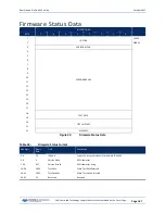
Страница 179: ... 9 10 11 12 13 14 15 16 17 18 TEST DATA 19 20 TEST SWITCHES 21 22 RESERVED Figure 39 Firmware Status Data Table 34 Firmware Status Format Hex Digit Binary Byte Field Description 1 4 1 2 ID Code Stores the status data identification word ID 4400h 4 6 3 Version Alpha ASCII character 7 34 4 17 Version Branch ASCII character string 35 38 18 19 Test Data Word Test Data Selected 39 42 20 21 Test Switche...

Страница 180: ...tores the vertical beam data identification word 00 41h 5 6 3 Eval Amp Contains the evaluation amplitude of the matching filter used in determining the strength of the bottom echo 7 8 4 RSSI Amp Contains the RSSI value for the sample at the middle of the bottom echo 9 16 5 8 Range to Bottom Contains the vertical beam range to the bottom Scaling LSD 1 mm Range 0 to 100000 mm 17 18 9 Status Contains...

Страница 181: ...e Leader Format BIT POSITIONS BYTE 7 6 5 4 3 2 1 0 1 VERTICAL BEAM PROFILE LEADER ID LSB 01 2 MSB 0F 3 NUMBER OF BINS 4 5 NUMBER OF PINGS PER ENSEMBLE 6 7 BIN SIZE 8 9 DISTANCE TO BIN 1 MIDDLE 10 11 RESERVED 12 13 TRANSMIT LENGTH 14 15 LAG LENGTH 16 17 NUMBER OF CODE ELEMENTS TRANSMITTED 18 19 RESERVED 40 Figure 41 Vertical Beam Profile Leader Format ...

Страница 182: ...n 1 middle Contains the distance to the middle of bin 1 The distance to the middle of bin 1 is determined by blank xmtLength lagLength binSize 2 Blank and bin size are affected by the speed of sound xmt length and lag use a fixed speed of sound value ZF Vertical Beam Blanking Distance determines blank ZS Vertical Beam Bin Size determines bin size which also determines xmt length unless the ZT xmt ...

Страница 183: ...ofile velocity identification word LSB 00 MSB 0A 5 8 3 4 Depth Cell 1 Velocity 1 Stores velocity data for depth cell 1 velocity 1 See above 8 804 5 402 Cells 2 200 if used These fields store the velocity data for depth cells 2 through 200 depending on the setting of the ZN Vertical Beam Number of Bins command These fields follow the same format as listed above for depth cell 1 Vertical Beam Profil...

Страница 184: ...ata for depth cell 1 beam 1 See above 7 404 4 202 Cells 2 200 if used These fields store echo intensity data for depth cells 2 through 200 for all four beams These fields follow the same format as listed above for depth cell 1 Table 40 Vertical Beam Profile Percent Good Data Format Hex Digit Binary Byte Field Description 1 4 1 2 ID Code Stores the vertical beam profile percent good data identifica...

Страница 185: ... 204 VTG 205 DBT 206 HDT 207 All others 200 9 12 5 6 Msg Size word size of NMEA message 13 30 7 14 Delta Time 8 byte IEEE double floating point format Difference between ensemble time and NMEA message receipt time 31 15 ASCII NMEA message The ASCII NMEA message received from the external device is inserted as re ceived The messages size is variable WinRiver II may add additional bytes For example ...

Страница 186: ...ONS BYTE 7 S 6 5 4 3 2 1 0 1 ID CODE LSB 00 2 MSB 32 3 Row 1 Col 1 4 5 Row 1 Col 2 6 7 Row 1 Col 3 8 9 Row 1 Col 4 10 11 Row 2 Col 1 12 13 Row 2 Col 2 14 15 Row 2 Col 3 16 17 Row 2 Col 4 18 19 Row 3 Col 1 20 21 Row 3 Col 2 22 23 Row 3 Col 3 24 25 Row 3 Col 4 26 27 Row 4 Col 1 28 29 Row 4 Col 2 30 31 Row 4 Col 3 32 33 Row 4 Col 4 34 Figure 45 Beam Correction Matrix Format ...

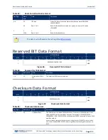
Страница 187: ...SB Figure 46 Reserved BIT Data Format Table 44 Reserved for TRDI Format Hex Digit Binary Byte Field Description 1 4 1 2 Reserved for TRDI s use This field is for TRDI internal use only Checksum Data Format BIT POSITIONS BYTE 7 6 5 4 3 2 1 0 1 CHECKSUM DATA LSB 2 MSB Figure 47 Checksum Data Format Table 45 Checksum Data Format Hex Digit Binary Byte Field Description 1 4 1 2 Checksum Data This field...

Страница 188: ...d has being fixed Fixed refers to units used for a given field the number of bytes in a given field and the order in which the fields appear within the data type Fixed does not refer to the total number of bytes in the data type see Rule 3 3 Data may be added to an existing data type only by adding the bytes to the end of the data format As an example the variable leader data contains information ...

Страница 189: ...ing the value of each byte The 2 byte least significant digits cal culated will be the checksum c Read the 2 byte checksum word at the end of the ensemble located by using the checksum offset in the header determined in step 2 a and compare this checksum word to the value calculated in step 2 b d If the checksums match then this is a valid ensemble If the checksums do not match then it is not a va...

Страница 190: ...October 2017 RiverPro and RioPro ADCP Guide Page 178 EAR Controlled Technology Subject to Restrictions Contained on the Cover Page NOTES ...

Страница 191: ...DCP Guide October 2017 EAR Controlled Technology Subject to Restrictions Contained on the Cover Page Page 179 Appendix A NOTICE OF COMPLIANCE In this chapter you will learn China RoHS requirements Material disclosure table ...

Страница 192: ...ur covered products as required in Chinese law and does not reflect in any way the safety quality or warranty associated with these TRDI products Some homogenous substance within the EIP contains toxic or hazardous substances or elements above the requirements listed in SJ T 11363 2006 These substances are identified in Table 47 WEEE The mark shown to the left is in compliance with the Waste Elect...

Страница 193: ...phenyl Ethers PBDE 换能器配件 Transducer Assy X X O X O O 机体装配 Housing Assy X O O O O O 接收机电路板 Receiver PCB X O O O O O 数据处理器电路板 DSP PCB X O O O O O 输入输出口电路板 PIO PCB X O O O O O 通讯接口板 Personality Module X O O O O O 蓝牙电路板 Bluetooth PCB X O O O O O 机体装配 Housing Assy X O O O O O 专用装运箱和泡沫塑料垫 Shipping Case w Foam O O O O O O O 表示该有毒或有害物质在该部件所有均质材料中的含量均在 SJ T 11363 2006 标准规定的限量要求以下 O Indicates that the toxic...

Страница 194: ...October 2017 RiverPro and RioPro ADCP Guide Page 182 EAR Controlled Technology Subject to Restrictions Contained on the Cover Page NOTES ...

Отзывы: