background image

3. Power-up Hardware
Power Button:

 The Power button illuminates when the unit is connected to a power source. Press and release the button 

to power on or power off the system. 

Status Indicators:

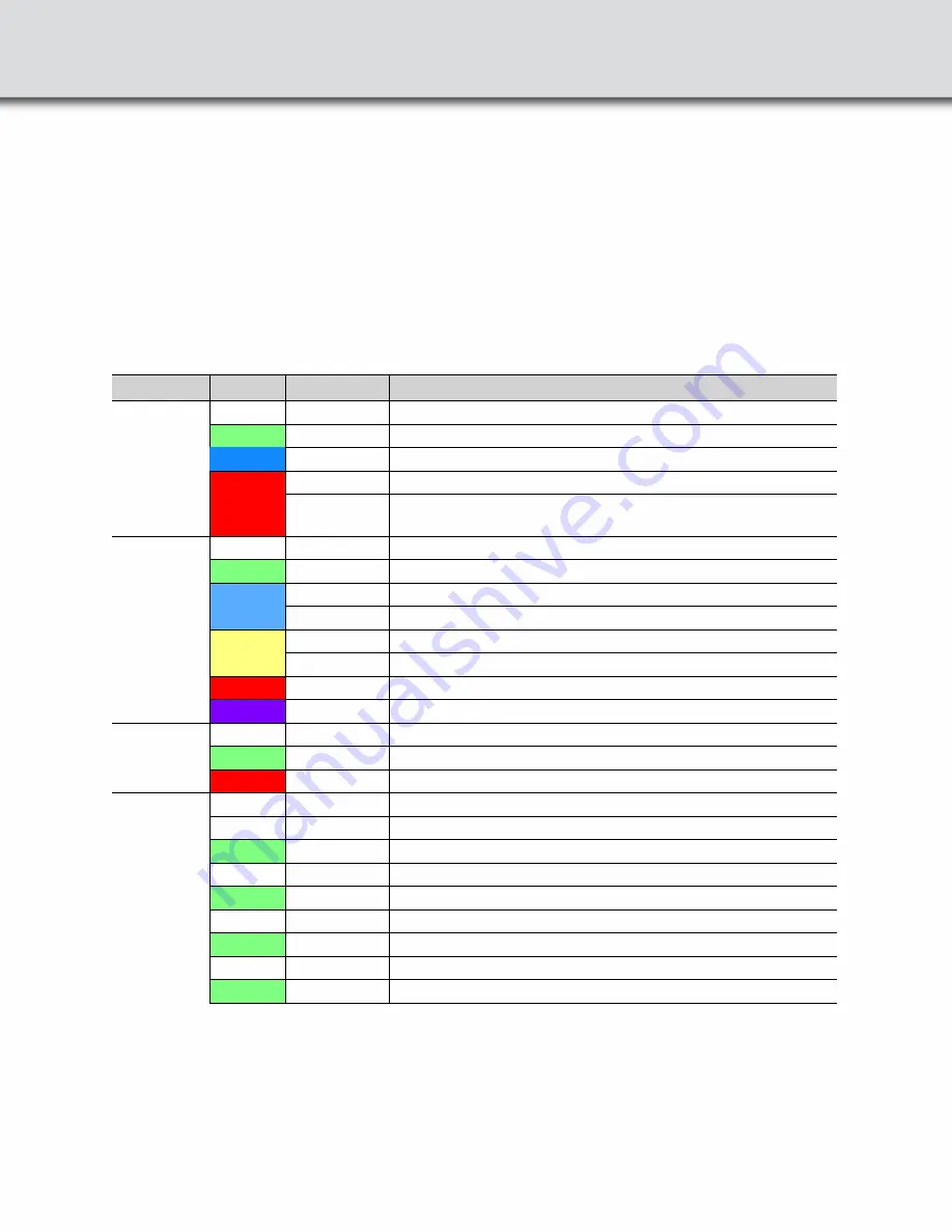
 Colored LEDs show the status of power, capture, and RF Status.

Table 1: X500 Front Panel Status Indicators

Indicator

Color

State

Status Indicated

Power

None

Off

Unit is powered off.

Green

Constant

Unit powered on with sufficient power source plugged in.

Blue

Constant

Unit powered on with sufficient power source plugged in.

Red

Fast Flash

Thermal warning threshold reached.

Solid

System reaches thermal overload. Unit has started a 

controlled/sequenced power down.

Status

None

Off

No Status.

Green

Constant

Initialized and Ready. Not Capturing.

Blue

Slow Flash

Waiting for Capture Trigger (future).

Solid

Actively capturing.

Yellow

Slow Flash

Initializing.

Fast Flash

Shutting down.

Red

Constant

The unit failed to initialize or has a System Error.

Purple

Constant

Recovery Mode.

BT Rx1

None

Off

Antenna not in use

Green

Constant

Antenna in use capturing.

Red

Fast Flash

Signal strength too strong.

BT Rx2

None 

Off

Reserved for future use.

Wi-Fi Rx1

None 

Off

Antenna not in use.

Green

Constant

Antenna in use capturing.

Wi-Fi Rx2

None 

Off

Antenna not in use.

Green

Constant

Antenna in use capturing.

Wi-Fi Rx3

None 

Off

Antenna not in use.

Green

Constant

Antenna in use capturing.

Wi-Fi Rx4

None 

Off

Antenna not in use.

Green

Constant

Antenna in use capturing.

Содержание Everywhereyoulook Frontline X500

Страница 1: ...ount for each of the system components listed on the accompanying packing list Visually inspect each component for any damage In the event of damage notify Teledyne LeCroy Retain all shipping materials for shipper s inspection The X500TM hardware does not contain any user serviceable items Any repairs and maintenance must be performed by a service technician that has been trained and approved by T...

Страница 2: ...with the product to the X500 hardware Connect to Host PC Connect one end of the USB C C 3 0 cable to the Host port on the X500 and connect another end to the 3 0 port on the host computer This will allow sending data from the hardware to the PC for the analysis Frontline X500 Rear Panel Controls 2 Attach Antennas Remove the Frontline X500 hardware from the box and attach the six antennas to the SM...

Страница 3: ...ted a controlled sequenced power down Status None Off No Status Green Constant Initialized and Ready Not Capturing Blue Slow Flash Waiting for Capture Trigger future Solid Actively capturing Yellow Slow Flash Initializing Fast Flash Shutting down Red Constant The unit failed to initialize or has a System Error Purple Constant Recovery Mode BT Rx1 None Off Antenna not in use Green Constant Antenna ...

Страница 4: ...e image Click X500 under Start Wireless Protocol Suite Start Page When the Wireless Protocol Suite window pops up you will see the following display with the Analyzer Toolbar that controls hardware record and configuration options Your unit is preconfigured with licensed features Wireless Protocol Suite software with Analyzer Toolbar 5 ...

Страница 5: ...analysis can be done while recording To analyze the data using the Wireless Protocol Suite select specific devices of interest to include in the analysis The Security pane shows all encrypted Bluetooth links The Status Bar shows a running total of captured packets Start Analyze On the Wireless Protocol Suite s Toolbar click the Start Analyze button or select Start Record from the Capture menu opti...

Страница 6: ...ile to the selected location Saving Analyzed Data To clear captured data click the Clear icon If you select Clear after stopping analysis and have not saved it already a message appears asking whether you want to save the data You can click Save File and enter a file name when prompted If you choose Do Not Save all data will be cleared If you choose Cancel the dialog closes with no changes 7 ...

Страница 7: ...Croy Customer Support Online Download Periodically check the Teledyne LeCroy Protocol Solutions Group web site for software updates and other support related to this product Web http www fte com products default aspx Sales Frontline_OnlineSales Teledyne com Support Frontline_Techsupport Teledyne com 2021 Teledyne LeCroy Inc All rights reserved Part Number 934094 00 Rev A This document may be print...

Страница 8: ......

Отзывы: