110
Teledyne API T500U CAPS NO
2
Analyzer with NumaView™ Software
083730510A DCN8172
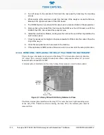
2. Turn off power to the instrument, fold down the rear panel by loosening the mounting
screws.
3. While looking at the electronic circuits from the back of the analyzer, locate the Disk-on-
Module in the right-most socket of the CPU board.
4. The DOM should carry a label with firmware revision, date and initials of the programmer.
5. Remove the nylon standoff clip that mounts the DOM over the CPU board, and lift the
DOM off the CPU. Do not bend the connector pins.
6. Install the new Disk-on-Module, making sure the notch at the end of the chip matches the
notch in the socket.
7. It may be necessary to straighten the pins somewhat to fit them into the socket. Press the
chip all the way in.
8. Close the rear panel and turn on power to the machine.
9. If the replacement DOM carries a firmware revision, re-enter all of the setup information.
REMOVING / REPLACING THE RELAY PCA FROM THE INSTRUMENT
This is the most commonly used version of the Relay PCA. It includes a bank of solid state
AC relays. This version is installed in analyzers where components such as AC powered
heaters must be turned ON & OFF.
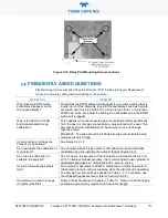
A retainer plate is installed over the relay to keep them securely seated in their sockets.
Figure 5-13. Relay PCA with AC Relay Retainer In Place
The Relay retainer plate installed on the relay PCA covers the lower right mounting screw
of the relay PCA. Therefore, when removing the relay PCA, the retainer plate must be
removed first.
Содержание T500U
Страница 2: ......

