


Page 45
Telect, Inc. • USA +1.509.926.6000 • 52.33.3836.37.52
www.telect.com • © 2011 Telect, Inc., All Rights Reserved, 139249-1 A0
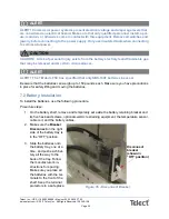
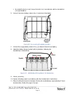
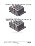
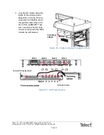
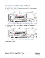
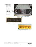
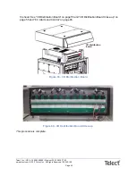
2. Loop the DC cables along the
inside of the enclosure and
bring them out to the Front ac-
cess power termination panel
through the cable entry in the
front of the nrgSMART™ sys-
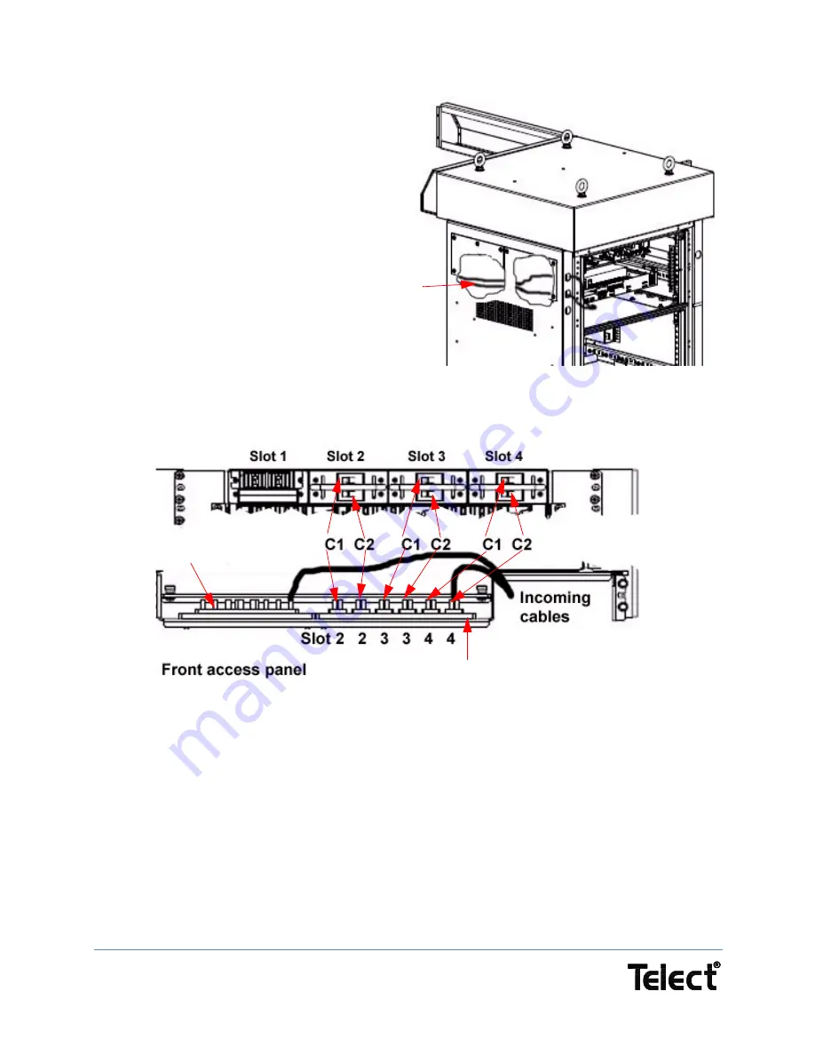
tem. The slots in the DC load
circuits correspond to the MDS
module circuit breakers.
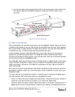
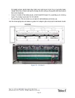
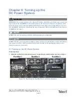
Figure 51 - DC Power System
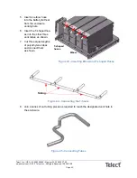
Incoming
cables
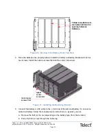
Figure 50 - Cables Looping Through to Front
DC load circuits
Common DC power return


