


TTM 01-G Manual / October 2018
8
A lightning protection device should be inserted into the antenna lead. A suitable device, complete with
additional cable connectors, a connector crimping tool and mounting hardware is available as an option. The
introduction of the lightning protector introduces an additional loss of 0.1 dB and the loss of two connectors.
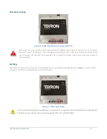
Care should be taken to ensure that the connector is not cross threaded when attaching the
antenna lead-in cable. The connector should be tightened by hand only. DO NOT OVER-
TIGHTEN!
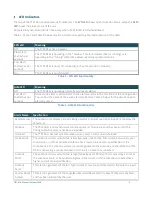
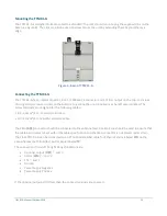
ETH: Ethernet Interface (ST Fiber / RJ-45)
TTM 01-G units are fitted with either an RJ-45 10/100 Mbps Ethernet interface or an ST multi-mode Fiber
100BASE-FX Ethernet interface. The unit can be configured over the LAN (Local Area Network) and can be
loaded with PTP or NTP / SNTP Licenses.
To the left of the Ethernet connector are two LEDs: The “
LNK
” LED (above) and the yellow “
ACT
” LED (below).
The LNK LED will be on when the unit is connected to a valid Ethernet port whilst the ACT LED will be on when
there is activity on either the transmit or receive pair on the Ethernet port.
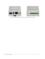
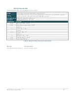
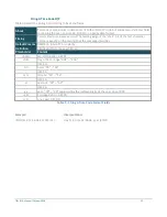
TX: Fiber Output
This port transmits an IRIG-B (B00x or B22x), programmable pulse or DCF77 signal over fiber, that may be
configured to output in either inverted or non-inverted polarity. The fiber transmitter is compatible with 50/125
µm, 62.5/125 µm and 100/140 µm multimode glass fiber.
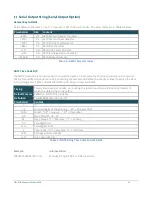
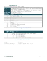
TTL: TTL Output
The TTL output is a high drive, non-isolated TTL level driver which can be configured using Tekron’s
Configuration Tool. This port transmits an IRIG-B (B00x or B22x), programmable pulse, or DCF77 signal using 0 –
5 Vdc TTL level on pins “+” and “-” of the screw terminal connector. The default output is an un-modulated IRIG-
B signal (IRIG-B004 with C37.118.1 extensions). It can be used as the master source signal to drive one or many
slave devices. The IRIG-B timing pulses (both leading and trailing edges) from this port is typically to within 100
ns of UTC.
This port is a programmable TTL level output that may be configured to output in either inverted or non-inverted
polarity:
•
A configurable number of pulses per second, minute, hour, day with adjustable pulse-width and offset.
•
IRIG-B time code (Un-modulated DCLS or Modified Manchester) with option C37.118.1 or AFNOR
extensions.
•
Simulated DCF77 receiver time code.