background image

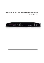
TQM  1616 

16


in


1


Mux


Scrambling


QAM


Modulator

User’s Manual

Содержание TQM 1616

Страница 1: ...TQM 1616 16 in 1 Mux Scrambling QAM Modulator User s Manual ...

Страница 2: ...ecifications 2 1 5 Appearance and description 3 Chapter 2 Installation Guide 5 2 1 Acquisition Check 5 2 2 Installation Preparation 5 2 3 Wire s Connection 7 2 4 Signal Cable Connection 7 Chapter 3 Web based NMS Management 9 3 1 login 9 3 2 Operation 9 Chapter 4 Troubleshooting 20 Chapter 5 Packing List 21 ...

Страница 3: ...h GE1 TQM1616 is also characterized with high integrated level high performance and low cost It supports dual power supply optional This is very adaptable to newly generation CATV broadcasting system 1 2 Features 16 DVB C DVB T T2 S S2 FTA Tuner 2 ASI input 512 IP input thru GE1 over UDP and RTP protocol 16 DVB C RF output 1 IP MPTS output over UDP and RTP RTSP as mirror of one carrier Support 16 ...

Страница 4: ...MHz Constellation 16 32 64 128 256 QAM DVB T T2 Frequency In 30MHz 999 999 MHz Bandwidth 6 7 8 M bandwidth DVB S S2 Input Frequency 950 2150MHz Symbol rate QPSK 1 45Mbauds 8PSK 1 45Mbauds Code rate 1 2 3 5 2 3 3 4 4 5 5 6 8 9 9 10 Demodulation Mode QPSK 8PSK ISDB T Input Frequency 170 860MHz ATSC Input Frequency 30MHz 1000MHz Bandwidth 6M Multiplexing Maximum PID Remapping 360 output per channel F...

Страница 5: ...tepping Constellation 16 32 64 128 256QAM J 83A J 83B Constellation 16 32 64 128 256QAM 64 256 QAM Bandwidth 8M 6M Stream out 16 RF output F type interface 1 IP MPTS output over UDP and RTP RTSP GE1 only as mirror of one carrier System Network management WEB Chinese and English language Ethernet software upgrade General Dimension W D H 482mm 300mm 44 5mm Temperature 0 45 Operation 20 80 Storage Po...

Страница 6: ... Manual 4 Rear Panel Illustration 4 NMS port Network management interface 5 Data port GE1 IP input and output port GE2 reserved for future 6 ASI input port 7 RF out port 1 16 channels RF IN Interface 2 Integrated power switch and socket 3 Grounding Wire ...

Страница 7: ...details of installation will be described at the rest part of this chapter Users can also refer rear panel chart during the installation The main content of this chapter including Checking the possible device missing or damage during the transportation Preparing relevant environment for installation Installing modulator Connecting signal cables Connecting communication port if it is necessary 2 2 ...

Страница 8: ...ditioning power and lighting power are independent to each other Device power requires AC power 100 240V 50 60Hz Please carefully check before running 2 2 3 Grounding Requirement All function modules good grounding is the basis of reliability and stability of devices Also they are the most important guarantee of lightning arresting and interference rejection Therefore the system must follow this r...

Страница 9: ...witch is on the left power supply socket is on the right and the fuse is just between them Connecting Power Cord User can insert one end into power supply socket while insert the other end to AC power Connecting Grounding Wire When the device solely connects to protective ground it should adopt independent way say share the same ground with other devices When the device adopts united way the groun...

Страница 10: ...TQM1616 16 in 1 Mux Scrambling QAM Modulator User s Manual 8 RF Input Loop Cable Illustration ASI input cable illustration ...

Страница 11: ...net cable and use ping command to confirm they are on the same network segment I G the PC IP address is 192 168 99 252 we then change the device IP to 192 168 99 xxx xxx can be 1 to 254 except 252 to avoid IP conflict Use web browser to connect the device with PC by inputting the Modulator s IP address in the browser s address bar and press Enter It will display the Login interface as Figure 1 Inp...

Страница 12: ...6 DVB S S2 DVB T T2 C Tuner input From the menu on left side of the webpage clicking Tuner1 16 it displays the information of each encoding channel as Figure 3 System language setting User can click any item here to enter the corresponding interface to check information or set the parameters System information ...

Страница 13: ...the menu on left side of the webpage clicking TS Config it displays the interface where users can configure the TS output parameters TS Config Output TS From the menu on top side of the webpage clicking Output TS X it displays the interface where users can select output TS channel Figure 4 Figure 4 ...

Страница 14: ...l which come from GE1 To edit the input channel To delete the input channel To delete all inputs channel To check input IP lock or not green means current IP locked To check current TS overflow or not red color means current TS overflow need to reduce program To filter not filter the source CA information To enable disable the PID remapping To refresh the input program information To refresh the o...

Страница 15: ...ion of parsing input programs Program Modification The multiplexed program information can be modified by clicking the program in the output area For example when clicking it triggers a dialog box Figure 6 where users can input new information Figure 6 TS Config General From the TS Config menu on up side of the webpage clicking General it displays the interface where users can set output mode enab...

Страница 16: ... Config PID Bypass Clicking PID Bypass it displays the interface as Figure 8 where user can add PIDs to be passed click the symbol input current IP channel number then input current IP source PID and output PID which is customer needed then click set to apply the parameters ...

Страница 17: ... Figure 9 Parameters Modulator From the menu on left side of the webpage clicking Modulator it displays the Modulator Configuration screen as Figure 10 Here user can set modulation parameters This field indicates the current outputting programs The programs selected will be scrambled CA channel select EMMG and ECMG working state green means it work normally while red means communication error or n...

Страница 18: ...a dialog box as follow where users can set all channels configration When users click Channel config button it triggers a dialog box as follow where users can set the corresponding channel configration Parameters IP Stream TQM1616 supports TS to output in IP 1 MPTS format as copy of one carrier Quickly Config Channel Config ...

Страница 19: ...al 17 through the DATA port Clicking IP Stream it displays the interface where to set IP out parameters Figure 12 Figure 12 System Network Clicking Network it displays the interface as Figure 13 where to set network parameters Click here to Config IP output ...

Страница 20: ...g Password it displays the screen as Figure 14 where to set the login account and password for the web NMS Figure 14 System Configuration From the menu on left side of the webpage clicking Configuration it will display the screen as Figure 15 where to save restore factory setting backup load your configurations Figure 15 System Firmware ...

Страница 21: ...the webpage clicking Firmware it will display the screen as Figure 16 where to update firmware for this modulator Figure 16 System Log From the menu on left side of the webpage clicking Log it will display the log interface as Figure 17 where to check or export the Kernel System log Figure 17 ...

Страница 22: ...to 45 C Making sure good ventilation for the heat sink on the rear panel and other heat sink bores if necessary Checking the input AC voltage within the power supply working range and the connection is correct before switching on device Checking the RF output level varies within tolerant range if it is necessary Checking all signal cables have been properly connected Frequently switching on off de...

Страница 23: ...TQM1616 16 in 1 Mux Scrambling QAM Modulator User s Manual 21 Chapter 5 Packing List 1pc 1pc TQM1616 16 in 1 Mux Scrambling QAM Modulator User s Manual Power Cord 1pc ...

Отзывы: