NOTE:
THIS INSTRUCTION
BOOKLET CONTAINS
IMPORTANT
SAFETY INFORMATION.
PLEASE READ AND KEEP FOR FUTURE REFERENCE.
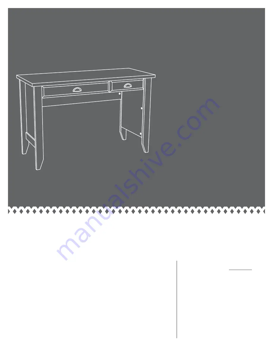
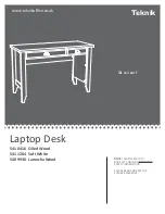
Laptop Desk
5410416
Oiled Wood
5411204 Soft White
5409936 Jamocha Wood
Sit
and
surf
.
www.teknikoffice.co.uk
Teknik
Страница 1: ...STRUCTION BOOKLET CONTAINS IMPORTANT SAFETY INFORMATION PLEASE READ AND KEEP FOR FUTURE REFERENCE Laptop Desk 5410416 Oiled Wood 5411204 Soft White 5409936 Jamocha Wood Sit and surf www teknikoffice c...
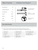
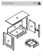
Страница 2: ...tion While not all parts are labeled some of the parts will have a label or an inked letter on the edge to help distinguish similar parts from each other Use this part identi cation to help identify s...
Страница 3: ...Part Identi cation Now you know our ABCs Page 3 A B C D E F G H I J K P P J D716 D20 D74 D21...
Страница 4: ...unit Page 4 ANGLE BRACKET 3 5G HIDDEN CAM 16 1F CAM COVER 7 13P PULL 2 27K CAM SCREW 10 8F SLIDE CAM 2 10A CAM DOWEL 6 2F 12H HINGE 2 40AW CABINET RIGHT 1 40AX CABINET LEFT 1 40AY DRAWER RIGHT 1 40AZ...
Страница 5: ...Page 5 GOLD 1 MACHINE SCREW 4 50S BLACK 9 16 LARGE HEAD SCREW 6 1S BLACK 2 1 4 FLAT HEAD SCREW 6 26S BROWN 1 FLAT HEAD SCREW 4 18S GOLD 5 16 FLAT HEAD SCREW 12 3S SILVER 5 8 FLAT HEAD SCREW 4 23S SILV...
Страница 6: ...DESTY PANEL E Then insert the metal end of six CAM DOWELS 2F into the HIDDEN CAMS in the ENDS A and B and UPRIGHT C Page 6 6 used A B C E 16 used 1F 1F 1F 1F Do not insert CAM DOWELS into this part Do...
Страница 7: ...B Tighten six HIDDEN CAMS Step 2 Page 7 A B H I J J H I 8F Curved edge 1 2 S u r f a c e w i t h H I D D E N C A M S S u r f a c e w i t h H I D D E N C A M S These surfaces should be even These surfa...
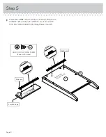
Страница 8: ...S rest on the surfaces of the ENDS Slide the SIDE MOLDINGS P onto the ENDS A and B Line up the grooves in the MOLDINGS over the heads of the SCREWS in the ENDS Page 8 A B P P Apply pressure with your...
Страница 9: ...the REAR LEGS J to the ENDS Use six BLACK 2 1 4 FLAT HEAD SCREWS 26S Step 4 Page 9 A B J J Curved edge S u r f a c e w i t h H I D D E N C A M S S u r f a c e w i t h H I D D E N C A M S BLACK 2 1 4 F...
Страница 10: ...the UPRIGHT C Use four GOLD 5 16 FLAT HEAD SCREWS 3S through holes 1 and 3 Page 10 1 2 3 4 A C 4 3 2 1 H S u r f a c e w i t h o u t H I D D E N C A M S GOLD 5 16 FLAT HEAD SCREW 4 used in this step...
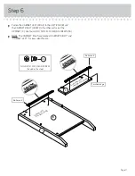
Страница 11: ...four GOLD 5 16 FLAT HEAD SCREWS 3S NOTE The CABINET RAILS are marked CABINET RIGHT and CABINET LEFT for easy identi cation Step 6 Page 11 C B I GOLD 5 16 FLAT HEAD SCREW 4 used in this step 3S Finish...
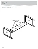
Страница 12: ...Step 7 Fasten the MODESTY PANEL E to the ENDS A and B Tighten four HIDDEN CAMS Page 12 B A E H I S u r f a c e w i t h H I D D E N C A M S These holes must be here...
Страница 13: ...G to the MODESTY PANEL E Use three BLACK 9 16 LARGE HEAD SCREWS 1S NOTE Be sure the edges of the ANGLE BRACKETS are even with the edge of the MODESTY PANEL Step 8 Page 13 E B A 5G BLACK 9 16 LARGE HEA...
Страница 14: ...WS 1S Page 14 E B A D BLACK 9 16 LARGE HEAD SCREW 3 used in this step 1S Long nished edge Start Tighten Arrow Minimum 190 degrees Caution Risk of damage or injury HIDDEN CAMS must be completely tighte...
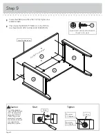
Страница 15: ...Fasten the UPRIGHT C to the TOP D Tighten two HIDDEN CAMS Step 10 Page 15 D C Arrow Minimum 190 degrees Maximum 210 degrees Finished edge Surface with HIDDEN CAMS Almost time to celebrate With a nap...
Страница 16: ...T HEAD SCREWS 23S Fasten the KEYBOARD HINGES 12H to the KEYBOARD SHELF F Use two SILVER 9 16 LARGE HEAD SCREWS 54S Page 16 F G 12H F i n i s h e d s u r f a c e SILVER 5 8 FLAT HEAD SCREW 4 used for K...
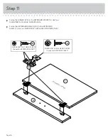
Страница 17: ...E The DRAWER SLIDES are marked DRAWER RIGHT and DRAWER LEFT for easy identi cation Fasten a PULL 27K to the KEYBOARD FRONT G Use two GOLD 1 MACHINE SCREWS 50S Step 12 Page 17 F G 27K Roller end Roller...
Страница 18: ...TTOM D716 into the grooves in the DRAWER SIDES D20 and D21 and DRAWER FRONT K The tabs should insert freely into the slots Gently tilt the DRAWER SIDES side to side until the tabs slip into the slots...
Страница 19: ...S D20 and D21 Use four GOLD 5 16 FLAT HEAD SCREWS 3S through holes 2 and 4 NOTE The screw head in the CAM must be visible through the slotted hole in the SLIDE 10A 10A Screw head turn the CAM to line...
Страница 20: ...Step 15 Fasten a PULL 27K to the DRAWER FRONT K Use two GOLD 1 MACHINE SCREWS 50S Page 20 K 27K GOLD 1 MACHINE SCREW 2 used for the PULL 50S...
Страница 21: ...on the drawer behind the rollers on the unit Lift the front of the drawer up and slide it into the unit Repeat this step to insert the KEYBOARD SHELF F Push a CAM COVER 13P onto each visible HIDDEN C...
Страница 22: ...DRAWER FRONT line up better when closed Tighten the SCREW when nished with adjustments NOTE Please read the back pages of the instruction booklet for important safety information This completes assemb...
Страница 23: ...y moving furniture that is not designed and equipped with casters Furniture can tip over or break if improperly moved Physical injury Furniture can be very heavy Breakage of tops particularly with dou...