C
L E A R
P
A T H
M C / S D
U
S E R
M
A N U A L
R
E V
.
3 . 0 9
9 6
T
EKNIC
,
I
NC
. T
EL
.
(585)
784-7454
M
ODE
C
ONTROLS
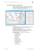
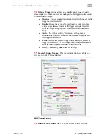
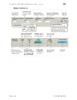
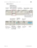
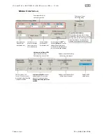
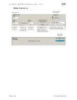
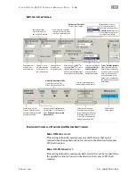
Enter max. torque
desired (i.e. full
scale torque).
Soft Inputs and LEDs
Emulate hardware inputs. For
use only when Soft Controls
are active.
Caution: motor
may spin when enabled.
Displays commanded
torque (when using
Soft Controls).
Displays commanded
torque (when using
hard controls).
Hardware Input Status LEDs
Light = Input asserted (on)
Dark = Input de-asserted (off)
PWM Meter -
Displays
duty cycle of PWM source
connected to Input B.
PWM Soft Slider
Emulates PWM
input (for use with
Soft Controls).
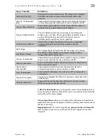
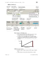
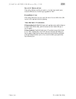
Check to turn on Soft
Controls. Override cannot
be activated when ClearPath
is hardware enabled.
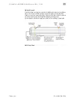
Enter value to specify how long
ClearPath can spin at
Max Speed
before shutting down.
Enter max. speed limit
(ClearPath will shut down if
this speed limit is exceeded.)
Click to open
Torque Limit
Setup dialog.
Displays HLFB
output status.
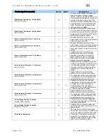
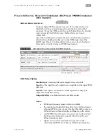
Torque Override Indicator
When lit, the main torque limit is being
overridden by a secondary, user-set torque
limit (e.g., when an axis is homing, the main
torque limit may be overridden by the
separate homing torque limit setting).
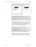
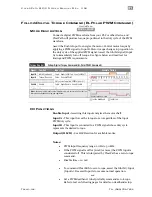
Check box to invert how PWM duty
cycle is measured by ClearPath.
NO CHECK
CHECK
Duty cycle is
% of period high
Duty cycle is
% of period low
Caption
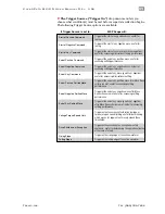
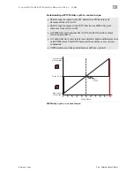
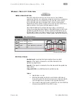
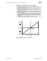
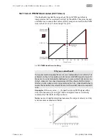
Motor torque vs. PWM duty cycle:
•
Motor torque is proportional to PWM duty cycle (i.e. torque
increases as duty cycle increases). See figure below.
•
0% and 100% duty cycle signals (static low and static high
respectively) are invalid PWM states, interpreted by ClearPath
as “PWM turned off”. This is the equivalent of a zero-torque
command.
0
50
100
PWM Duty Cycle (%)
Torque
Max. Torque
(user set)
0
PWM duty cycle vs. torque
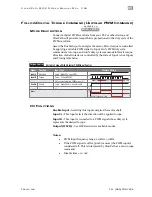
•
For CW torque, set Input A high. For CCW torque, set Input A
low.
•
PWM minimum on time and minimum off time = 300nS

