background image

C

L E A R

P

A T H  

M C / S D


U

S E R  

M

A N U A L  

R

E V

.


3 . 0 9  

8 2


T

EKNIC

,


I

NC

. T

EL

.


(585)


784-7454 

S

COPE 

U

SER 

I

NTERFACE 

&


C

ONTROLS


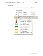
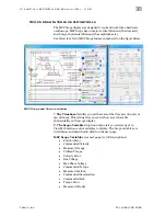
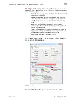
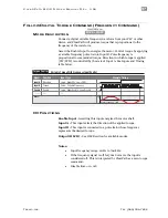
The MSP Scope display was designed to look and work like a hardware 
oscilloscope. MSP Scope has 10 major vertical divisions (the time axis), 
and 8 major horizontal divisions (the amplitude axis). 

See below for a list of MSP Scope features numbered on the figure below. 


MSP Scope and Cursors window 

1


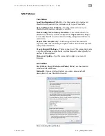
The Timebase

 field lets you set the scale of the time axis (in units of 

ms/division). This setting lets you control how a waveform fits 
(horizontally) on the scope display. 

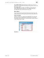
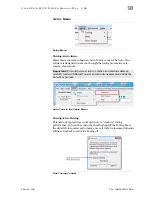
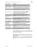
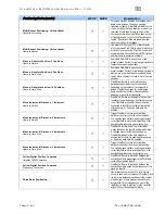
The Scope Variable

 drop down menu lets you select any of 13 

ClearPath motion control variables to display. The Scope variables are 
listed below and described in detail on the next page. 

MSP Scope Variables (see next page for full descriptions) 


Position Error 


Commanded Velocity 


Measured Torque 


Utilized Torque 


Velocity Error 


Bus Voltage 


Max Phase Voltage 


Commanded Torque 


Measured Position 


Commanded Acceleration 


Commanded Jerk 


Torque Error 


Measured Velocity 


Содержание CLEARPATH CPM-MCVC-3421S-RLN

Страница 1: ...USER MANUAL CLEARPATH USER MANUAL MODELS MCVC MCPV SDSK SDHP NEMA 23 AND NEMA 34 FRAME SIZES VERSION 3 09 JUNE 30 2020 ...

Страница 2: ...C L E A R P A T H M C S D U S E R M A N U A L R E V 3 0 9 2 TEKNIC INC TEL 585 784 7454 THIS PAGE INTENTIONALLY LEFT BLANK ...

Страница 3: ...INGS 23 Personal Safety Warnings 23 CE Compliance Warnings 23 General Disclaimer 24 INTRODUCTION 25 What is a ClearPath Motor 25 Parts of a ClearPath Motor 27 Example Application Absolute Positioning Mode 28 Summary of Operation 28 Overview Configuring a ClearPath 29 Overview ClearPath I O 30 POWERING A CLEARPATH SYSTEM 31 Selecting a DC Bus Power Supply 31 ClearPath Operating Voltage 31 Notes on ...

Страница 4: ...s 60 Installing MSP 60 Communicating With ClearPath Via MSP 60 Items Required for Communication Setup 61 First Time Communication Setup 61 Tour of ClearPath MSP Software 62 Main UI Overview 62 Mode Controls 62 Torque Limit Setup 63 Dashboard 68 MSP Menus 69 MSP Software Scope 81 Overview 81 Scope Features 81 Scope User Interface Controls 82 OPERATIONAL MODES MCVC AND MCPV 89 Table of Operational M...

Страница 5: ... Command Unipolar PWM Input 114 Mode Description 114 I O Functions 114 Mode Controls 115 Follow Digital Velocity Command Frequency Input 117 Mode Description 117 I O Functions 117 Mode Controls 118 Move to Sensor Position 119 Mode Description 119 I O Functions 120 Mode Controls 121 Move to Absolute Position 2 Position Home to Switch 122 Mode Description 122 I O Functions 122 Mode Controls 123 Move...

Страница 6: ...ription 142 I O Functions 142 Mode Controls 143 Multi Sensor Positioning Unidirectional Home to Sensor 144 Mode Description 144 I O Functions 144 Mode Controls 145 Follow Digital Position Command Unipolar PWM Command 146 Mode Description 146 I O Functions 146 Mode Controls 147 Follow Digital Position Command Frequency Command 148 Mode Summary 148 I O Functions 148 Mode Controls 149 OPERATIONAL MOD...

Страница 7: ...PENDIX D COMMON SPECIFICATIONS 172 APPENDIX E GROUNDING AND SHIELDING 173 Protective Earth PE Connection 173 Grounding and Shielding 173 Power Returns 174 APPENDIX F CIRCUIT SCHEMATICS 175 POWER4 HUB Schematic simplified 175 APPENDIX G CLEARPATH PART NUMBER KEY 176 APPENDIX H MISCELLANEOUS TOPICS 177 Homing 177 Introduction 177 Terms Used In This Section 178 Homing Settings 179 Typical Homing Sequ...

Страница 8: ... but we do want all ClearPath users to stay safe and fully intact These devices are very powerful and can be extremely dangerous if used carelessly Please read and understand all safety warnings in the ClearPath User Manual before operating a ClearPath motor BEFORE YOU BEGIN SUGGESTED VIEWING MATERIAL Check out the ClearPath overview video This is a great way to learn about ClearPath motors and Te...

Страница 9: ...p file to your local computer extract the exe file and run it SECURE YOUR MOTOR Injury Warning To prevent broken toes and damage to your motor always secure your ClearPath motor to a stable flat level work surface before operating it otherwise your motor will buck and jump during operation A quick grip style clamp or vise is recommended Tip If you use a vise to secure your motor you can preserve t...

Страница 10: ... not made by Teknic For Teknic DC power cables PN CPM CABLE PWR MS120 test DC voltage at pins 3 and 2 as shown below pin 3 is v and pin 2 is GND This should display a positive voltage reading 2 GND 4 Teknic IPC 5 Power Supply VDC ClearPath Voltage Range 24 75VDC 1 3 V Power Connector Molex 4 pin Polarity test from pin 3 V to pin 2 GND shows a positive 75 volts POWER UP YOUR CLEARPATH 1 Begin with ...

Страница 11: ... a minute or so Damage Warning Do not use USB cables of unknown origin e g found in a junk drawer with your ClearPath Non standard cables may be incompatible with ClearPath and may even damage your motor Micro B Type A Windows PC Win 7 8 1 10 with MSP application installed ClearPath Motor USB Comm Port Teknic Part CPM CABLE USB 120 Connect ClearPath to your PC OPEN CLEARPATH MSP MOTOR SETUP PROGRA...

Страница 12: ...est development and training but are not meant to be used as the control system for your machine SPINNING A MODEL MCPV OR MCVC Spinning Step Direction models SDSK and SDHP is covered in the next section For models MCPV and MCVC we will use the mode Ramp Up Down To Selected Velocity Feel free to try any mode available in the Mode drop down menu Each mode is described in its own section later in thi...
Страница 13: ... V 3 0 9 13 TEKNIC INC TEL 585 784 7454 3 Select Mode Velocity Ramp Up Down to Selected Velocity 4 A dialog window will open see below Please read all of the text presented especially if you re unfamiliar with how the op mode works Click OK to proceed ...
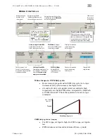
Страница 14: ...e Displayscommandedvelocity whenusing hardinputs Displayscommandedvelocity whenusing softinputs HardwareInputStatusLEDs Light Inputasserted on Dark Inputde asserted off ChecktoturnonSoft Controls Overridecannot beactivatedwhenClearPath ishardwareenabled AdjustsettingsforRASTM or optionalg StopTM toconvert standardtrapezoidalmove profilesintoprofilesthatreduce noise resonance andvibration Clicktoop...

Страница 15: ...ecktode energize InputAControl CheckheretoassertInputA Unchecktode assert InputBControl CheckheretoassertInputB Unchecktode assert Check Override Inputs box to turn on Soft Controls 7 Safety check Before proceeding make sure that the motor is securely clamped down and the shaft is safely positioned away from fingers clothing hair cables etc 8 Click the Enable Control Caution the motor is now energ...

Страница 16: ...ties Feel free to experiment Try changing velocities accelerations and RAS settings 10 RPM A on B off 0 RPM A off B off 100 RPM A off B on 500 RPM A on B on Change velocity and direction by checking Inputs A and B ADDITIONAL NOTES The direction of shaft rotation is set by entering a or sign in front of the velocity settings see top of figure above will cause CCW rotation will cause CW rotation ...

Страница 17: ... models MCVC and MCPV is covered in the previous section ClearPath SD models have one mode Step and Direction We ll open that mode and get the motor spinning using MSP software controls 1 Open MSP software 2 Establish USB communication to your motor 3 The Tuning dialog will appear For now select the bottom option run with no load and hit Next ...

Страница 18: ...is turns on the software controls You may notice that the other Soft Controls are no longer grayed out SoftControls Usetoemulatehardwareinputs OverrideInputs CheckheretoturnonSoftControls Note Overridecannotbeactivated whenClearPathishardwareenabled EnableControl Checktoenergizemotorwindings Unchecktode energize Jogmotor clockwise Jogmotorcounter clockwise Check Override Inputs to turn on Soft Con...

Страница 19: ...le checkbox Caution the motor is now energized and capable of motion Enable using Soft Controls 10 Make some moves With the motor enabled click the jog button Change direction by checking Input A Test different velocity and acceleration settings Click and hold to jog buttons to spin your ClearPath SD motor ...

Страница 20: ... field at lower right of the UI This does not mean that the motor is broken Try lowering the acceleration and or velocity of your moves until the warning goes away The majority of shutdowns are caused by weak power supplies mechanical problems and or inappropriate settings If your ClearPath experiences a shutdown it is reporting a problem but is not necessarily causing the problem You can clear mo...

Страница 21: ... for use with motor drives such as Teknic s IPC 3 or IPC 5 series or use a beefy bulk linear power supply with at least 10 000 microfarads of capacitance Don t use a weak switching power supply STARTING THE AUTO TUNER In MSP click Setup Auto tune Start the Auto Tuner Important The Auto Tune application was carefully designed to walk users through the tuning process in a safe step by step manner An...

Страница 22: ...versions If your power supply is a switcher or an underpowered bulk linear supply with insufficient current and or capacitance and cannot tolerate regenerated energy you ll have problems running Auto Tune ClearPath motors can operate between 24 and 75 VDC but they require adequate power to Auto Tune Issue My ClearPath is getting shutdowns A shutdown seldom means your ClearPath is broken or defecti...

Страница 23: ...ting to operate a ClearPath motor Install and test all emergency stop devices and controls before using ClearPath Before applying DC power secure the ClearPath motor to a stable solid work surface and install a finger safe guard or barrier between the user and the motor shaft Provide appropriate space around the ClearPath motor for ventilation and cable clearances Do not allow cables or other loos...

Страница 24: ...igher than the electrical connection end of the motor the USB connector plug provided by Teknic must be installed The USB plug in these installations becomes an element to prevent the spread of fire per EN 61010 1 section 9 3 2 part c GENERAL DISCLAIMER The User is responsible for determining the suitability of products for their different applications The User must ensure that Teknic s products a...

Страница 25: ...e earth magnets and encoder technology The servo drive electronics and motion control firmware employ the same state of the art technology and advanced motion control algorithms as our high end non integrated servo control products ClearPath Simplicity begins with a quick uncomplicated setup Install the included MSP software connect ClearPath to your PC via USB and configure and tune your ClearPat...

Страница 26: ...be reprogrammed to perform a different job in just a few minutes Safety and self protection features are standard ClearPath will rapidly shut down if it becomes overloaded overheated detects a hard stop or exceeds any of the safety or motion limits you specify Made in USA Each ClearPath motor is built and tested in our New York manufacturing facility so you can be certain you re getting a high qua...

Страница 27: ... this 4 position Molex MiniFit Jr connector I O Connector Access ClearPath s three inputs and one output through this 8 position Molex MiniFit Jr connector Configuration Port Use this port to connect ClearPath to a Windows PC with a standard USB Type A to Micro B cable Cover port with included silicone plug when not in use Status LED Tri color LED Indicates operational status of ClearPath device S...

Страница 28: ... in this section Windows PC With USB port Running MSP software Set Operational Mode Set speeds and accelerations Set move distances Manage options Perform tuning Monitor system performance DC Power Supply Range 24 75VDC Signal Source to ClearPath Inputs 3 Inputs 5 24VDC Compatible PLC Switches Sensors Encoder Microcontroller HLFB High Level Feedback 5 24VDC Compatible User settable Move Done mode ...

Страница 29: ...reaches a specified speed or torque or shuts itself down for safety reasons See the section on Outputs High Level Feedback for more on HLFB modes OVERVIEW CONFIGURING A CLEARPATH ClearPath must be configured and tuned before it can be used in a motion application The main configuration steps are outlined below Each of these points is discussed in greater detail later 1 Install ClearPath software M...

Страница 30: ... 24VDC 5 24VDC User Inputs Switches PLC Micro controller Sensors Signal generator High Level Feedback Output ClearPath I O Connector Simplified overview of ClearPath inputs and output Enable Input Asserting the Enable input logical 1 high 5 24VDC energizes the motor coils Deasserting Enable logical 0 low state 0 volts removes power from the motor coils Inputs A and B Once enabled ClearPath can res...

Страница 31: ...urrent and handling back EMF reverse voltage generated by the spinning motor that cancels a portion of the incoming supply voltage A power supply specifically designed for motor drive power like Teknic s Intelligent Power Center supplies IPC 3 and IPC 5 will have these features and are ideal for servo systems like ClearPath Bulk linear power supplies basically a transformer rectifier and large cap...

Страница 32: ...Auto Tune cannot run to completion you probably have an underpowered supply ClearPath completes the auto tuning process but experiences certain warnings or shutdowns during programmed motion If Auto Tune runs to completion but you experience torque saturation voltage saturation or both during regular machine operation you may be exceeding the supply s voltage and or current capability If you have ...

Страница 33: ...ite www teknic com for more information features and specifications TEKNIC MODEL IPC 5 The IPC 5 fully enclosed power supply can typically power two to six ClearPath motors The actual number depends on the application fewer when the motors are generating high torque continuously at high speeds and more when the motors are intermittently using bursts of power like in many point to point positioning...

Страница 34: ...ng the DC output side especially with inexpensive relays will ultimately result in poor performance drop outs due to pitting corrosion and contact welding If a power switch is required install it such that the supply is disconnected from the AC input side see figure below POWER SUPPLY FUSING If you require an external fuse on your power supply s DC output to meet compliance standards for example i...

Страница 35: ...earPath motors chaining power from motor to motor may be preferable You will have to fabricate power cables as shown below to chain power from motor to motor Power Supply IPC 5 shown ClearPath Motors 2 GND 1 V 4 GND 3 V Power Connector Pinout Connector Housing 4 pos Molex 39 03 9042 black Terminals 16AWG Molex 39 00 0078 loose Molex 39 00 0077 reel Crimp Tool 16 24 AWG Molex 63819 0900 Terminal Ex...

Страница 36: ...er backup keeps the motors electronics alive even if DC bus power is dropped This translates to uninterrupted communication continuous status monitoring and retention of encoder position Note You will be unable to spin your motors when using only logic power backup Logic power backup will keep the motor electronics alive but is not designed to run motors POWER HUB OVERVIEW DIAGRAM Power Hub ClearP...

Страница 37: ...ould not be used as a means of switching DC bus power on and off To control DC bus power use a contactor on the AC side of the DC bus power supply Do not connect more than two Power Hubs to a power supply Continuous and peak current usage must not exceed the power supply s specifications It is the user s responsibility to ensure that the DC bus power supply has sufficient continuous and peak power...

Страница 38: ...llel The other connector can be used to daisy chain bus power to a second Power Hub if desired or left unconnected DC Bus Power Outputs Qty 4 These four connectors supply bus power to your ClearPath motors In addition if power is dropped they carry aux power to keep maintain motor communication to the host application They are fully short circuit protected 24VDC Logic Power Input with Passthrough ...

Страница 39: ...V 3 0 9 39 TEKNIC INC TEL 585 784 7454 CONNECTIONS FOR A SINGLE POWER HUB SYSTEM 75VDC Bus Input Passthrough 75VDC Bus Out x4 24VDC Aux Supply IPC 5 75VDC Bus Supply ClearPath Motors AC Source 110 220VAC 75VDC Bus Out Power Hub Single Power Hub System ...

Страница 40: ...C Bus Out x4 75VDC Bus In 75VDC Bus In 24VDC Aux Supply IPC 5 75VDC Bus Supply AC Source 110 220VAC 75VDC Bus Out Power Hub Two Power Hubs powering 8 ClearPath motors AUXILIARY 24V LOGIC POWER SUPPLY The Power Hub requires 24VDC to function This is labeled as 24VDC Aux Supply above See appendix Logic Power Supply Sizing for power budgeting information Note Never use the main DC bus power supply ev...

Страница 41: ...onnects bus input from bus output in this case as a protective measure Normal operation OVERTEMP Board Thermal Shutdown Red Board temperature has exceeded 105 C Note After an overtemp event LED will turn off when board temp falls below 95 C Normal operation Board temp is 105 C DROPOUT 75V Dropout LED Red Bus supply has dropped out meaning the DC Bus has fallen below 18 2 VDC Aux power is active No...

Страница 42: ... to the Power Hub Connecting and disconnecting the motor from a live power supply will cause electrical arcing that will pit and carbonize connectors over time Do not attempt to power more than four ClearPath motors from a single Power Hub Do not connect more than two Power Hubs to a power supply Continuous and peak current usage must not exceed the power supply s specifications Important While it...

Страница 43: ... Input A 7 Input A 2 Input B 6 Input B 1 HLFB output 5 HLFB output Connector Housing 8 position Molex 39 03 9082 black Terminals 22 28 AWG Molex 39 00 0047 loose Molex 39 00 0046 reel Crimp Tool 16 24 AWG Molex 63819 0900 Terminal Extractor Tool Molex 11 03 0044 Mating Parts I O Connector Pinout Cable Stock 8 22AWG Belden 9421 Note NEMA 34 motor shown at left NEMA 23 models have 4 pin and 8 pin co...

Страница 44: ...Enable 4 8 Input A Input A 3 7 Input B Input B 2 6 Current Limiter Current Limiter Current Limiter 5 24 VDC 5 24 VDC 5 24 VDC ClearPath Internal External Circuit ClearPath Inputs shown with simple switches INPUT CURRENT DRAW The table and graph below illustrate the maximum current draw by the ClearPath input circuits for the range of acceptable input voltages Voltage at ClearPath Input Minimum Inp...

Страница 45: ...must also add a common diode such as part number 1N4004 to the circuit to prevent the inductor s back EMF from destroying the ClearPath input circuit Note when a diode is used in this manner it is often called a flyback diode snubber suppression diode or catch diode Information on the Web For more information search Wikipedia Flyback Diode for an article that explains how a circuit with an inducti...

Страница 46: ...ower Up mode Enable With Trigger function In a few ClearPath modes the Enable input also serves as a trigger input In these modes briefly pulsing the Enable input low and immediately back high again causes ClearPath to perform a predefined action such as execute a move change direction of rotation or change velocity See individual operation modes for trigger mode details INPUTS A AND B THE CONTROL...

Страница 47: ...IN Current Limiter V IN IN Current Limiter V IN IN Current Limiter NPN Sinking Open Collector PNP Sourcing 1k IN IN Current Limiter V Signal Signal Sourcing Sinking Signal low Input asserted Signal high Input asserted ClearPath Input ClearPath Input ClearPath Input ClearPath Input Transistor Outputs Driven Outputs Single Ended Interfacing digital outputs to ClearPath Inputs Engineer s Note 5V diff...

Страница 48: ...tdown Servo On mode When the commanded move is complete and settled to the user s specifications ASG Position mode How well the motor is following your positioning or velocity commands In Range Motor speed via PWM output Speed Output mode Motor position via PPR output Pulses Per Revolution Motor torque via PWM output Torque Output mode Note The HLFB circuit is not internally powered it requires an...

Страница 49: ... In Servo On mode the HLFB output asserts conducts when ClearPath is enabled and not in a shutdown state This signal is often used to monitor ClearPath for shutdowns or as the control signal for an external brake Note the HLFB circuit cannot directly drive an external brake SPEED OUTPUT In Speed Output mode the HLFB outputs a 45 Hz or 482 Hz user selectable PWM waveform whose duty cycle varies in ...

Страница 50: ...ses will exhibit a 50 duty cycle When the motor shaft is stopped the HLFB output can be either fixed high or fixed low As long as the motor maintains logic power the output will produce pulses corresponding to motor shaft rotation even if the motor is disabled or in a shutdown MEASURED TORQUE In Measured Torque mode the HLFB outputs a 45 Hz or 482 Hz user selectable PWM waveform that varies in dut...

Страница 51: ...fy Time PWM Active Not in Range In Range HLFB Timing HLFB output modes available only in ClearPath positioning op modes IN RANGE POSITION The HLFB output asserts conducts when the motor is enabled not shutdown and the measured motor position is In Range X encoder counts of the current commanded position The In Range parameters are set in the HLFB Setup dialog ASG ALL SYSTEMS GO POSITION In ASG Pos...

Страница 52: ...G Position with Measured Torque works in the same way as ASG Position except during commanded motion the HLFB outputs a 45 Hz or 482 Hz user selectable PWM waveform that varies in duty cycle between 5 and 95 to indicate direction and magnitude of motor shaft torque as follows 5 duty cycle 100 peak torque CW direction 50 duty cycle zero torque 95 duty cycle 100 peak torque CCW direction ASG POSITIO...

Страница 53: ...PWM DUTY CYCLEVARIESWITHTORQUE At Target Velocity Verify Time PWM Active Not in Range In Range v v HLFB Timing HLFB output modes available only in ClearPath velocity op modes ASG ALL SYSTEMS GO VELOCITY In ASG Velocity mode the HLFB output asserts conducts when the motor is enabled not shutdown and is At Target Velocity At Target Velocity occurs when the motor has settled within X of the final tar...
Страница 54: ... waveform that varies in duty cycle between 5 and 95 to indicate direction and magnitude of motor shaft torque as follows 5 duty cycle 100 peak torque CW direction 50 duty cycle zero torque 95 duty cycle 100 peak torque CCW direction ASG VELOCITY LATCHED WITH MEASURED TORQUE ASG Velocity Latched with Measured Torque is a combination of all the previous ASG Velocity modes During commanded accelerat...

Страница 55: ...or is enabled not shutdown and is producing the commanded torque The HLFB output deasserts non conducting when the motor is disabled shutdown or if the motor cannot produce the commanded torque for one of the following reasons The supplied bus voltage is not high enough for the motor to produce the commanded torque at the current motor velocity The motor is at or above the max motor speed setting ...

Страница 56: ... A SINKING OUTPUT The HLFB output can be used as a sinking output as shown below This topology provides ClearPath with a high level of immunity from damage if for example the circuit is shorted to machine chassis Such a short would simply make the output appear like a closed circuit Note the preceding assumes the DC supply return is connected to chassis ground at one location in the machine ClearP...

Страница 57: ... from an external device should be limited to 30mA maximum Although ClearPath includes built in current limiting a series connected current limiting resistor may still be necessary to protect the HLFB Output s internal circuitry A series resistor of 2000Ω 24VDC 1100Ω 12VDC 500Ω 5VDC can help prevent an overloaded or blown circuit Note Any circuit or external device that you intend to connect to th...

Страница 58: ... it requires an external 5 24VDC power supply capable of sourcing sinking at least 1mA non inductive In typical HLFB applications power is supplied by the PLC control board or an external supply See Appendix D for complete HLFB specifications User Circuit HLFB HLFB Current Limiter ClearPath Internal 1 5 5 24VDC HLFB Driving LED HLFB Driving a Brake Via Solid State Relay ClearPath s HLFB output cir...

Страница 59: ...9 TEKNIC INC TEL 585 784 7454 1 4 2 3 S O L I D S T A T E R E L A Y OUTPUT INPUT HLFB HLFB Current Limiter ClearPath Internal 5 1 5 24VDC Inductive loads must be diode suppressed INPUT OUTPUT Brake 24VDC Crydom DC60S3 HLFB circuit controlling an SSR brake setup ...

Страница 60: ...ssor 1 GHz or faster Memory 512 MB HD Free Space 512 MB Monitor 1280 x 1024 pixels or higher Other Sound card with speakers optional INSTALLING MSP Download the MSP installer from Teknic s website Follow the on screen prompts to complete installation COMMUNICATING WITH CLEARPATH VIA MSP After MSP is installed on your PC follow the directions below to establish a communication link between your Cle...

Страница 61: ...Requirements 2 Power up ClearPath Apply 24 75VDC to the power input connector 3 Connect ClearPath to your PC with a USB Type A to Micro B cable 4 Wait In most cases Windows will detect the connected ClearPath and install the correct USB driver software automatically This step can take a few minutes to complete Proceed only after Windows reports the device is installed and ready for use 5 Launch MS...

Страница 62: ...ated to the currently selected mode These parameters include position acceleration velocity torque limits homing parameters and more Access Soft Controls Soft Controls allow you to spin your ClearPath with no external hardware required With just MSP a powered up ClearPath motor and a USB cable you can enable the motor turn the inputs on and off command motion and monitor the HLFB output state Soft...

Страница 63: ...you to specify different torque limits for each direction of travel and dynamic torque limits based on motor position Zone Limits To open the Torque Limit dialog click the Setup button in the Mode Controls section see figure below Direction of Applied Torque Positive torque torque applied in the counterclockwise direction of rotation looking into the motor shaft Negative torque torque applied in t...

Страница 64: ...DVANCED TORQUE LIMIT SETTINGS Select Advanced Settings to open additional torque limit settings including Torque Zone Limiting and Symmetric vs Independent Torque Limiting more detail on these features below Click Show to open Advanced Torque Limit Settings Advanced Torque Limit Setup dialog ...

Страница 65: ...tion Limit1 90 Themotorcanapplyupto 90 ofitspeaktorqueinthe counterclockwisedirection Limit2 90 Themotorcanapplyupto 90 ofitspeaktorqueinthe clockwisedirection 90 CCW 90 CW Symmetric Torque Limits Independent Torque Limits Select Independent Limits if you want to set different torque limits for each direction of travel Limit1 50 Themotorcanapplyupto 50 ofitspeaktorqueinthe counterclockwisedirectio...

Страница 66: ...along an axis of travel See example below Note The ClearPath system must be homed to use Zone Limits In this zone torque applied in the positive CCW direction will be limited to 10 of peak torque In this zone torque applied in the negative CW direction will be limited to 20 of peak torque Main Torque Limit applies in this section 0 20 000 80 000 100 000 Load 1 2 1 2 50 000 Zone Torque Limits Norma...

Страница 67: ...ring clamping 3 Set Zone Move Done Style to Clamped Application Tip When moving the motor into a clamping position you must send enough pulses to ensure that the motor is fully pressed into the object being clamped In this zone torque applied in the positive CCW direction will be limited to 5 of peak torque In this zone torque applied in the negative CW direction will be limited to 5 of peak torqu...

Страница 68: ...on Messages Displays message associated with any active ClearPath exception condition Emergency Stop Button Click here or hit Esc on keyboard to de energize motor coils Toggle Enable to restore operation Motor Status Description ClearPath is disabled Enable is de asserted Motor coils are not energized ClearPath is enabled via user hardware Caution Motor is energized and capable of motion ClearPath...

Страница 69: ...faults will cause the motor s existing configuration data to be overwritten Export XML file Ctrl L Teknic support use This command exports an XML file containing a snapshot of the current Soft Scope data and system information Create Support Package Teknic support use This command creates a zip file containing comprehensive system diagnostic data typically for use by a Teknic engineer Firmware Upd...

Страница 70: ...f MSP Click this menu item to reset RMS Max this is the maximum RMS value recorded since last motor reset MODE MENU Select ClearPath operating modes from this drop down menu Note the number and type of available operating modes varies by ClearPath model Motion Generator The Motion Generator is a special op mode that allows you to command test moves and jog your ClearPath motor using software contr...

Страница 71: ...tep manner Important To avoid personal injury crashes and machine damage carefully read and follow all on screen instructions presented during the Auto Tune process Auto Tune in the Setup Menu Tuning Fine Tuning This menu item provides a convenient way to touch up tuning performance Turn on the control by checking Apply Fine Tuning Move the slider left for quieter performance move it right for inc...

Страница 72: ...ration Velocity and acceleration can be displayed in terms of encoder counts or RPM Distances are always displayed in encoder counts Units Selection Menu Show Scope This option opens MSP s built in software oscilloscope Scope for short for troubleshooting and diagnostics See section MSP Software Scope for more detailed information on the features and functions of the MSP Scope ...

Страница 73: ...dvanced Menu High Level Feedback Abbreviated HLFB This is ClearPath s digital output The HLFB dialog lets you choose from several different HLFB modes HLFB can send a signal to indicate things like move completion turn on brake motor has shut down and several more For more details on HLFB modes and timing please refer to the Inputs and Outputs chapter of this manual High Level Feedback dialog set ...

Страница 74: ...ed Note Main DC bus power must be on at all times in this scenario Result If Position Recovery is on and if Homing is set to Home on first enable after power up or turned off enabling the motor will cause it to automatically return to its last commanded position at the specified velocity and acceleration Position Recovery Example 2 Your motor was operating but then loses DC bus power for a short p...

Страница 75: ... U A L R E V 3 0 9 75 TEKNIC INC TEL 585 784 7454 Disable Actions This dialog lets you tell ClearPath what stopping method to use when the motor is disabled either dynamic braking decelerate under power or coast to a stop Action Upon Disable ...

Страница 76: ...ror is the difference between ClearPath s commanded position and its actual position in units of encoder counts The phrase Tracking error is used interchangeably with the phrase position error throughout this manual Tracking Error Limit Setup Input A B Filtering This dialog lets you independently set digital filtering for the two ClearPath inputs This can be helpful when bouncy mechanical switches...

Страница 77: ...e Foldback This dialog allows you to automatically limit ClearPath s available torque when ClearPath has achieved Move Done status The Move Done Criteria consist of two parameters the In Range Window and the Verify Time For complete information please read the dialog window below Move Done Criteria Setup ...

Страница 78: ...n or just issue a warning when DC bus voltage falls below the minimum operating voltage setting as can happen when a power supply droops View the temperature of your ClearPath motor s circuit board Set the temperature threshold at which ClearPath throws an over temperature shutdown This should typically remain at the default setting Power and Temperature Settings ...

Страница 79: ...pics include the following o System Manual Select this option to navigate directly to the user manual for your specific product o Mode Video Select this option to navigate to the demo video or manual o Getting Started This option will take you directly to a video that explains how to initially set up your ClearPath motor The video walks you through different MSP features and parameters The video a...

Страница 80: ...you can view various demo videos featuring each ClearPath operational mode o TekTips Videos This option will take you to the Teknic Videos page where you can watch different tutorials on topics ranging from Auto Tune to Teknic s RAS feature to the differences between Stepper motors and ClearPath servo motors o Status Output HLFB Help Click this menu item to be taken directly to the HLFB section in...

Страница 81: ...se who routinely analyze and troubleshoot electrical mechanical and motion related problems on machines with ClearPath motors To open the scope in MSP navigate to Setup Show Scope Opening the MSP Scope SCOPE FEATURES 13 scope variables 4 trigger modes Adjustable time base range reference zero level and trigger position Dual Trace Capability 2 stored traces 2 live traces Twelve trigger source prese...

Страница 82: ...imebase field lets you set the scale of the time axis in units of ms division This setting lets you control how a waveform fits horizontally on the scope display 2 The Scope Variable drop down menu lets you select any of 13 ClearPath motion control variables to display The Scope variables are listed below and described in detail on the next page MSP Scope Variables see next page for full descripti...

Страница 83: ...x Phase Voltage displays the greatest voltage running through ClearPath s phase wires Torque Commanded Commanded torque displays the required torque to complete the given command from your controller or MSP Position Measured Measured Position displays the actual position of ClearPath in terms of encoder counts Acceleration Commanded Commanded Acceleration shows the actual acceleration command comi...

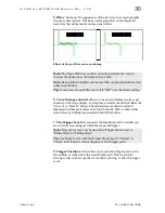
Страница 84: ...ay one trace per channel on the scope display Just capture a waveform and click either the Store A or Store B button The selected trace is then stored and displayed in either pink Store A or blue Store B Hide or show either stored trace by clicking its associated Show Hide button 7 The Trigger Level lets you select the amplitude of the variable you are currently measuring at which the scope will t...

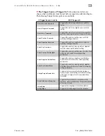
Страница 85: ...igger at the end of any move positive or negative after Move Done criteria are met useful for assessing settling performance Trigger on first occurance of saturation voltage or torque or upon speed limiting useful for determining which moves or segments of moves exceed these thresholds Trigger on the assertion of an exception or safety shutdown useful for determining the operational status at the ...

Страница 86: ...valid trigger source is detected After the single sweep capture data collection automatically stops Auto This is the scrolling always on setting Data is continuously collected refreshed and displayed regardless of the trigger source setting Force Forces the scope to trigger immediately regardless of trigger source setting As with Single mode only one data set is collected and displayed then data c...

Страница 87: ...ding delta calculation showing the difference between cursor values Zoom Between button allows one click magnification of the area of the scope display between the vertical cursors Measure Move button automatically places the vertical cursors at the beginning and end of a live move Hide and Show buttons let you view or hide vertical and or horizontal cursors as desired Reset button automagically r...

Страница 88: ...a number of additional events and conditions that occur in sync with the primary waveform capture Using the Strip Chart you can view move status mv drive events drv and I O states in real time And because the Strip Chart display is always auto synchronized to the main scope trace there are no settings to deal with MSP Strip Chart ...

Страница 89: ...olar PWM Command with Variable Torque Follow Digital Velocity Command Unipolar PWM Command Follow Digital Velocity Command Frequency Command Connect a digital waveform PWM or frequency from your PLC or other device and ClearPath will run at a velocity proportional to the waveform Or use the PWM output from an H bridge driver of a brushed motor setup and ClearPath becomes a high performance drop in...

Страница 90: ...e 1 Increment Home to Switch ClearPath will make an incremental move when the state of Input A changes If automatic homing is on ClearPath will seek for the home switch connected to Input B the first time it is enabled after power up or if desired each time it is enabled Move Incremental Distance 2 Increments Home to Switch Trigger ClearPath to move a user defined distance one of two from its curr...

Страница 91: ...xample Timing Notes Asserting Inhibit Input causes immediate jump to zero torque See text for information on deadband set up and application 0 1 0 1 Inside deadband Inhibit on Duty cycle of applied PWM signal Follow Digital Torque Command Bi Polar PWM Command Torque Control 90 50 20 I O FUNCTIONS Enable Input Asserting this input energizes the motor shaft Input A This input forces the torque to ze...

Страница 92: ...oft Controls Overridecannot beactivatedwhenClearPath ishardwareenabled Enterdeadbandsetting optional Seetextfor descriptionofdeadband operation Clicktoopen TorqueLimit Setupdialog DisplaysHLFB outputstatus Entermax desired motortorque i e fullscaletorque Entermax speedlimit ClearPathwillshutdownif thisspeedlimitisexceeded Entervaluetospecifyhowlong ClearPathcanspinatMaxSpeed beforeshuttingdown Che...

Страница 93: ...ction as PWM duty cycle increases from 50 to 100 As PWM duty cycle approaches 50 from either direction motor torque approaches 0 O and 100 duty cycle static low and static high conditions are not valid PWM states ClearPath interprets these values as zero torque commands PWM minimum on time and minimum off time 300nS Max Torque CCW Rotation Torque 0 Zero Torque 10 20 30 40 50 60 70 80 90 100 0 Max ...

Страница 94: ...W Rotation 5 PWM deadband setting Why use a deadband In bi polar mode turning off torque is achieved in theory by applying a 50 duty cycle PWM signal to Input B However it can be difficult to set a perfect 50 duty cycle In fact a very small amount of torque may still be produced by the motor even when duty cycle is apparently set to 50 A deadband helps guarantee torque is fully off when you expect...

Страница 95: ...Function Input Type Input A Motor torque vs time Input B Enable Direction Torque Enable NA NA Trigger Logic High CW Low CCW Pulse Variable PWM Logic High Enable Low Disable 0 1 0 1 t tq Example Timing Notes 0 1 0 1 Duty cycle of applied PWM signal 90 10 OFF Variable Torque With Unipolar PWM Input Control Torque Control I O FUNCTIONS Enable Input Asserting this input energizes the motor shaft Input...

Страница 96: ...lshutdownif thisspeedlimitisexceeded Clicktoopen TorqueLimit Setupdialog DisplaysHLFB outputstatus TorqueOverrideIndicator Whenlit themaintorquelimitisbeing overriddenbyasecondary user settorque limit e g whenanaxisishoming themain torquelimitmaybeoverriddenbythe separatehomingtorquelimitsetting Checkboxto inverthowPWMduty cycleismeasuredbyClearPath NOCHECK CHECK Dutycycleis ofperiodhigh Dutycycle...

Страница 97: ...e below Signal Function Input Type Input A Motor torque vs time Input B Enable Direction Torque Enable NA NA Trigger Logic High CW Low CCW Pulse Variable Frequency Logic High Enable Low Disable 0 1 0 1 t tq Example Timing Notes 0 1 0 1 Variable Torque With Frequency Input Control Torque Control I O FUNCTIONS Enable Input Asserting this input energizes the motor shaft Input A This input selects the...

Страница 98: ...rridecannot beactivatedwhenClearPath ishardwareenabled Clicktoopen TorqueLimit Setupdialog DisplaysHLFB outputstatus SetMin MaxFrequency During operation motortorqueiscontrolledby InputBsignalfrequency Withsettings shownbelow a10kHzinputsignalwill commandthemotortoitsMaxTorque Command 10 ofpeak andasignalof 1kHzorless willcommandzerotorque Entermax desired motortorque i e fullscaletorque Entermax ...

Страница 99: ...H LOW LOW HIGH HIGH HIGH Tip Setting one of the programmable velocities to zero Velocity 3 in the example at right provides a convenient way to stop the motor via the ClearPath inputs Velocity 1 Velocity 2 Velocity 3 Velocity 4 Ramp Up Down to Selected Velocity 4 Velocity Programmable Velocity Control Ramp Up Down to Selected Velocity Mode Inputs and Timing Diagram I O FUNCTIONS Enable Input Asser...

Страница 100: ...velocity whenusing hardinputs Displayscommandedvelocity whenusing softinputs HardwareInputStatusLEDs Light Inputasserted on Dark Inputde asserted off ChecktoturnonSoft Controls Overridecannot beactivatedwhenClearPath ishardwareenabled AdjustsettingsforRASTM or optionalg StopTM toconvert standardtrapezoidalmove profilesintoprofilesthatreduce noise resonance andvibration ClicktoopenTorque LimitSetup...

Страница 101: ...loaded ClearPath application for stopping behavior before deploying Signal Function Input Type Input A Motor velocity vs time Input B Disabled Disabled Disabled NA NA Main Power NA NA NA 0 1 0 1 0 1 t v Example Timing Caution Motor shaft may spin as soon as main power is applied Notes All inputs are ignored in this mode High Level Feedback is available Motor will free wheel when main power is remo...

Страница 102: ...Entermaximum desiredmotor decelerationrate ClicktoopenTorque LimitSetupdialog DisplaysHLFB outputstatus AdjustsettingsforRASTM or optionalg StopTM toconvert standardtrapezoidalmove profilesintoprofilesthatreduce noise resonance andvibration TorqueOverrideIndicator Whenlit themaintorquelimitisbeing overriddenbyasecondary user settorque limit e g whenanaxisishoming themain torquelimitmaybeoverridden...

Страница 103: ...which direction the encoder is turned i e whether phase A leads B or B leads A Signal Function Input Type Input A Motor velocity vs time Input B Enable Velocity Control A Velocity Control B Enable NA NA Trigger Quadrature Quadrature Logic High Enable Low Disable 0 1 0 1 0 1 t v Example Timing Notes Manual Velocity Control Velocity Control Knob encoder rotation reversed I O FUNCTIONS Enable Input A...

Страница 104: ...ical incremental encoder for this task but a microcontroller or digital signal generator will work as well A B C Enable Enable 4 8 Input A Input A 3 7 Input B Input B 6 2 Current Limiter Current Limiter Current Limiter 5 24 VDC ClearPath Internal 5 24 VDC Grayhill PN 25LB22 Q Example Wiring a Mechanical Quadrature Output Device to ClearPath OUTPUT A OUTPUT B COMMON C Grayhill PN 25LB22 Q 1 2 3 4 5...

Страница 105: ...perquadraturetick Reversesenseofmotor directionwithrespectto quadraturephasing orleave As Wired Eliminatesneedto rewireinputsifmotorrotates the wrong wayinitially HardwareInputStatusLEDs Light Inputasserted on Dark Inputde asserted off HasDetents Checkbox Seetext fordescription Clicktoopen TorqueLimit Setupdialog DisplaysHLFB outputstatus AdjustsettingsforRASTM or optionalg StopTM toconvert standa...

Страница 106: ...ction with respect to the quadrature device phasing HAS DETENTS CHECKBOX When unchecked ClearPath treats each quadrature transition it sees as a single tick Remember each tick causes an incremental change in motor speed When checked ClearPath treats every 4th quadrature transition it sees as one tick Remember each tick causes an incremental change in motor speed Check this box when using an encode...

Страница 107: ...isable 0 1 0 1 t v Example Timing Notes Asserting Inhibit Input causes immediate ramp to zero speed See text for information on deadband set up and application 0 1 0 1 Inside deadband Inhibit on Duty cycle of applied PWM signal Follow Digital Velocity Command Bi Polar PWM Command Velocity Control 90 50 10 I O FUNCTIONS Enable Input Asserting this input energizes the motor shaft Input A This input ...

Страница 108: ...latehardwareinputs For useonlywhenSoftControls areactive Caution motor mayspinwhenenabled Entermaximum desiredmotor decelerationrate Displayscommanded velocity whenusing SoftControls Displayscommanded velocity whenusing hardcontrols HardwareInputStatusLEDs Light Inputasserted on Dark Inputde asserted off PWMMeter Displays dutycycleofPWMsource connectedtoInputB PWMSoftSlider EmulatesPWM input forus...

Страница 109: ...as PWM duty cycle increases from 50 to 100 As PWM duty cycle approaches 50 from either direction motor velocity approaches 0 In practice O and 100 static low and static high conditions are not valid PWM states ClearPath treats these cases as zero velocity commands PWM minimum on time and minimum off time 300nS Max Velocity CCW Rotation Velocity 0 Zero Velocity 10 20 30 40 50 60 70 80 90 100 0 Max ...

Страница 110: ...e a deadband In bi polar mode stopping the motor i e commanding zero velocity is achieved in theory by applying a 50 duty cycle PWM signal to Input B However it can be technically challenging to set a perfect 50 duty cycle In fact some very low speed motion may still be observed at the motor shaft even when duty cycle is apparently set to 50 A deadband helps to ensure that actual motor velocity is...

Страница 111: ...Velocity Control Input B Motor velocity is controlled by sending a PWM signal to Input B Velocity is commanded as follows Shaft velocity increases in the CW direction as PWM duty cycle decreases from 50 to 0 Shaft velocity increases in the CCW direction as PWM duty cycle increases from 50 to 100 As PWM duty cycle approaches 50 from either side motor velocity approaches 0 In practice O and 100 stat...

Страница 112: ...rying the PWM duty cycle sent to Input A as follows Apply a 0 duty cycle static low to operate using purely the standard Torque Limits Apply a 100 duty cycle static high to operate using purely the Alternative Torque Limits Apply a duty cycle anywhere in between 0 and 100 to create a linear combination of the two limits Additional Notes PWM input frequency range 20 Hz up to 30 kHz If the PWM signa...

Страница 113: ...D Light Inputasserted on Dark Inputde asserted off PWMMeter Velocity Displaysdutycycleof PWMsignalconnected toInputB PWMMeter Torque Limiting Displaysduty cycleofPWMsignal connectedtoInputA InputB PWMSoftSlider EmulatesPWMinput for usewithSoftControls DisplaysHLFB outputstatus ChecktoturnonSoft Controls Override cannotbeactivated whenClearPathis hardwareenabled InputA PWMSoftSlider EmulatesPWMinpu...

Страница 114: ...otor velocity vs time Input B Enable Direction Velocity Enable NA NA Trigger Logic High CW Low CCW Pulse Variable PWM Logic High Enable Low Disable 0 1 0 1 t v Example Timing Notes 0 1 0 1 Duty cycle of applied PWM signal 90 10 OFF Follow Digital Velocity Command Unipolar PWM Command Velocity Control I O FUNCTIONS Enable Input Asserting this input energizes the motor shaft Input A This input selec...

Страница 115: ...sHLFB outputstatus AdjustsettingsforRASTM oroptional g StopTM toconvertstandardtrapezoidal moveprofilesintoprofilesthatreduce noise resonance andvibration TorqueOverrideIndicator Whenlit themaintorquelimitisbeing overriddenbyasecondary user settorque limit e g whenanaxisishoming themain torquelimitmaybeoverriddenbythe separatehomingtorquelimitsetting Checkboxto inverthowPWMduty cycleismeasuredbyCl...

Страница 116: ...A R P A T H M C S D U S E R M A N U A L R E V 3 0 9 116 TEKNIC INC TEL 585 784 7454 For CW shaft rotation set Input A high For CCW shaft rotation set Input A low PWM minimum on time and minimum off time 300nS ...

Страница 117: ... Frequency Logic High Enable Low Disable 0 1 0 1 t v Example Timing Notes 0 1 0 1 Follow Digital Velocity Command Frequency Input Control Velocity Control I O FUNCTIONS Enable Input Asserting this input energizes the motor shaft Input A This input selects the direction of rotation Input B This input is connected to a pulse train whose frequency represents the desired speed Output HLFB See HLFB sec...

Страница 118: ...equencyMeter Displaysfrequencyof inputsignalsource connectedtoInputB SoftInputsandLEDs Emulatehardwareinputs For useonlywhenSoftControls areactive Caution motor mayspinwhenenabled Displayscommanded velocity whenusing SoftControls FrequencySoftSlider Emulatesfrequency inputsource foruse withSoftControls ChecktoturnonSoft Controls Overridecannot beactivatedwhenClearPath ishardwareenabled DisplaysHLF...

Страница 119: ...arPath moves CW or CCW until it interrupts a sensor It then holds position until you issue a new User Command in the opposing direction See table below for Input states and timing details Signal Function Example Timing Move to Sensor Position Position Control Wired in series with Input A Wired in series with Input A Wired in series with Input B Wired in series with Input B Input A CW Move Request ...

Страница 120: ...ed when you view the motor with the shaft pointing toward you When a switch interrupts the move input the motor will begin to decelerate so the stopped position will be a repeatable distance beyond the switch Make sure you leave enough room after the sensor to avoid hitting the end stops ClearPath will not allow two successive moves in the same direction so you don t have to worry about the motor ...

Страница 121: ...erted on Dark Inputde asserted off ChecktoturnonSoft Controls Overridecannot beactivatedwhenClearPath ishardwareenabled Entermaxvelocity desired forCWrotation Entermaxvelocity desiredforCCWrotation DisplaysHLFB outputstatus AdjustsettingsforRASTM or optionalg StopTM toconvert standardtrapezoidalmove profilesintoprofilesthatreduce noise resonance andvibration TorqueOverrideIndicator Whenlit themain...

Страница 122: ...e Position 1 could be defined as 5200 encoder counts from home while Position 2 might be defined as 2000 encoder counts from home Signal Function Input Type Input A Motor position vs time Input B Enable Position Select Home Switch Enable NA NA Trigger Logic High Pos 2 Low Pos 1 Logic High Home Low Not Home Logic High Enable Low Disable 0 1 0 1 t p p Example Timing Notes ClearPath must home to a sw...

Страница 123: ...nd Input B high as not in the home switch Disable time 10 mS MODE CONTROLS HardwareInputStatusLEDs Light Inputasserted on Dark Inputde asserted off SoftInputsandLEDs emulate hardwareinputs Foruseonly whenSoftControlsareactive Caution motormayspinwhen enabled ChecktoturnonSoft Controls Overridecannot beactivatedwhenClearPath ishardwareenabled DisplaysHLFB outputstatus Entermax desired motorspeed En...

Страница 124: ...uts has the dual effect of selecting target position and triggering the move See table below for timing and input details All moves execute at the user defined speed and acceleration Signal Function Position Settings Example Timing Input A Motor position vs time Input B Enable Position Select A Position Select B Enable NA NA Trigger Logic High Enable Low Disable 0 1 0 1 0 1 0 1 t p p Pos 1 Pos 2 P...

Страница 125: ...ogic Power Backup LPB state using a ClearPath POWER4 HUB board The main bus power must be off To teach a position deassert the Enable input with the motor in the position you want to teach or deassert the Enable and then move the axis by hand to the desired spot Set inputs A and B to the binary state you want to teach and assert the Enable input The current location will then be linked to the curr...

Страница 126: ...orspeed Entermax desired accelerationrate Clicktoopen Homing Setupdialog SetTargetPositions Entermovedistance from home foreachinputstate Clicktoopen TorqueLimit Setupdialog AdjustsettingsforRASTM or optionalg StopTM toconvert standardtrapezoidalmove profilesintoprofilesthatreduce noise resonance andvibration TorqueOverrideIndicator Whenlit themaintorquelimit isbeingoverriddenbya secondary user se...

Страница 127: ...r the move Example to move to target position 9 you would send 9 pulses to input B Then you would trigger the move by sending a single pulse to Input A ClearPath would then move to position 9 at the user defined speed and acceleration Signal Function Input Type Input A Motor position vs time Input B Enable Trigger Position Select Enable Pulse input to select target position Pulse to start move on ...

Страница 128: ...verridecannot beactivatedwhenClearPath ishardwareenabled DisplaysHLFB outputstatus Entermax desired motorspeed Entermax desired accelerationrate Clicktoopen Homing Setupdialog SetTargetPositions Entermovedistance from home foreachindexposition Clicktoopen TorqueLimit Setupdialog AdjustsettingsforRASTM or optionalg StopTM toconvert standardtrapezoidalmove profilesintoprofilesthatreduce noise resona...

Страница 129: ...nable Increment Select A Increment Select B Enable Trigger Pulse Enable line to trigger moves Trigger Logic High Enable Low Disable 0 1 0 1 t p p Example Timing Notes ClearPath can be programmed to home upon enable see text for full details Moves are triggered on rising edge of trigger pulse Trigger pulse 0 1 LOW LOW HIGH LOW LOW HIGH HIGH HIGH D1 D2 D2 D2 D3 D4 D1 D1 Incremental Positioning 4 Dis...

Страница 130: ...nts the burst of trigger pulses must be sent rapidly The pulse train must be received by the ClearPath during the acceleration through constant velocity portion of move but not during the deceleration phase If a trigger pulse is received during the deceleration phase of a running move it will not be chained to the original move In fact the late pulse will trigger a separate move ...

Страница 131: ...t Setupdialog Clicktoadjust triggerpulsetiming AdjustsettingsforRASTM or optionalg StopTM toconvert standardtrapezoidalmove profilesintoprofilesthatreduce noise resonance andvibration TorqueOverrideIndicator Whenlit themaintorquelimit isbeingoverriddenbya secondary user settorquelimit e g whenanaxisishoming themaintorquelimitmaybe overriddenbytheseparate homingtorquelimitsetting HardwareInputStatu...

Страница 132: ... and acceleration Briefly pulse the Enable input to execute the next move at the alternate speed limit Signal Function Input Type Input A Motor position vs time Input B Enable Increment Position Increment Select Enable Trigger Pulse Enable line for Alternate Speed Trigger Logic Low Dist 1 High Dist 2 Start move on rising or falling edge Logic High Enable Low Disable 0 1 0 1 t p p Example Timing No...

Страница 133: ...ysHLFB outputstatus Entermax desired motorspeed Entermax desired accelerationrate Usethesecontrolsto setdifferentspeedsand accelerationsforeach positionincrement Clicktoopen Homing Setupdialog Clicktoopen TorqueLimit Setupdialog Clicktoadjust triggerpulsetiming AdjustsettingsforRASTM or optionalg StopTM toconvert standardtrapezoidalmove profilesintoprofilesthatreduce noise resonance andvibration T...

Страница 134: ...ional Enable Trigger Pulse Enable line low to trigger moves Trigger Logic Low Dist 1 High Dist 2 Logic High Home Low Not Home Logic High Enable Low Disable 0 1 0 1 t p p Example Timing Notes ClearPath can be programmed to home upon enable see text for full details Moves are triggered on rising edge of trigger pulse 0 1 Home D2 D2 D2 D1 D1 Trigger pulse Incremental Positioning 2 Incremental Distanc...

Страница 135: ...ccelerationrate Usethesecontrolsto setdifferentspeedsand accelerationsforeach positionincrement Clicktoadjust triggerpulsetiming AdjustsettingsforRASTM or optionalg StopTM toconvert standardtrapezoidalmove profilesintoprofilesthatreduce noise resonance andvibration HardwareInputStatusLEDs Light Inputasserted on Dark Inputde asserted off SoftInputsandLEDs emulate hardwareinputs Foruseonly whenSoftC...

Страница 136: ...lternate speed limit Signal Function Input Type Input A Motor position vs time Input B Enable Start Move Home Switch Enable Trigger Pulse Enable line for Alternate Speed Trigger Logic High Home Low Not Home Start move on rising or falling edge Logic High Enable Low Disable 0 1 0 1 t p p Example Timing Notes ClearPath can be programmed to home upon enable see text for details Moves can be triggered...

Страница 137: ...wareinputs Foruseonly whenSoftControlsareactive Caution motormayspinwhen enabled ChecktoturnonSoft Controls Overridecannot beactivatedwhenClearPath ishardwareenabled DisplaysHLFB outputstatus Entermax desired motorspeed Entermax desired accelerationrate Clicktoopen Homing Setupdialog Clicktoopen TorqueLimit Setupdialog Clicktoadjust triggerpulsetiming AdjustsettingsforRASTM or optionalg StopTM toc...

Страница 138: ...ocity vs time Input B Enable Direction Select Pulse Input Enable Speed Select Pulse low to select alternate speed Trigger Logic High CW Low CCW Pulse High Speed Pulse Burst Logic High Enable Low Disable 0 1 0 1 t v Example Timing Notes ClearPath requires a minimum pulse width 1uS Pulses less than 1uS will be filtered out as noise by ClearPath 0 1 Trigger pulse cc_mcsd Pulse Burst Positioning Pulse...

Страница 139: ...rnonSoft Controls Overridecannot beactivatedwhenClearPath ishardwareenabled DisplaysHLFB outputstatus TorqueOverrideIndicator Whenlit themaintorque limitisbeingoverriddenbya secondary user settorque limit e g whenanaxisis homing themaintorque limitmaybeoverriddenby theseparatehomingtorque limitsetting Checktoreverse directionofmotor shaftrotation Automaticallydisplays allowablerangeof inputpulsefr...

Страница 140: ... Example Timing Notes ClearPath must be homed before use Moves are triggered on rising edge of trigger pulse 0 1 Home P1 P1 P2 P2 P3 Trigger pulse Multi Sensor Position Bi directional Home to Hard Stop Position Control I O FUNCTIONS Enable Input Asserting this input energizes the motor shaft A short pulse user definable on this input is the trigger that starts a move A pulse is a momentary interru...

Страница 141: ...aft Selectwhethera sensoractuation turnsInputBonoroff Selectsensor discoverymethod Clicktoopen Homing Setupdialog Clicktoopen TorqueLimit Setupdialog Clicktoadjust triggerpulse timing Automaticallydisplays the distance pastasensorthata motorwillstop givencurrent settingsforspeed accel and RAS gStop AdjustsettingsforRASTM or optionalg StopTM toconvert standardtrapezoidalmove profilesintoprofilestha...

Страница 142: ... 0 1 t p p Example Timing Notes ClearPath can be programmed to home upon enable see text for details User may select rising or falling edge for input action via MSP setup software This diagram shows moves starting on the falling edge of Input A and stopping on the falling edge of Input B Pulse Enable to execute next move at alternate speed 0 1 Home Trigger pulse Trig Alt speed Multi Sensor Positio...

Страница 143: ...ggerpulse timing Automaticallydisplays the distance pastasensorthata motorwillstopgiventhe currentsettingsforspeed accel andRAS gStop AdjustsettingsforRASTM or optionalg StopTM toconvert standardtrapezoidalmove profilesintoprofilesthatreduce noise resonance andvibration TorqueOverrideIndicator Whenlit themaintorquelimit isbeingoverriddenbya secondary user settorquelimit e g whenanaxisishoming them...

Страница 144: ...witch operating polarity in MSP Diagram shows moves stop on rising edge transition of Input B User may specify either rising or falling edge in MSP sens 1 sens 2 sens 6 sens 3 1 2 3 4 5 6 Multi Sensor Position Unidirectional Home to Sensor Position Control I O FUNCTIONS Enable Input Asserting this input energizes the motor shaft A short pulse user definable on this input is the trigger that starts...

Страница 145: ...pulse timing Automaticallydisplays the distance pastasensorthata motorwillstopgiventhe currentsettingsforspeed accel andRAS gStop AdjustsettingsforRASTM or optionalg StopTM toconvert standardtrapezoidalmove profilesintoprofilesthatreduce noise resonance andvibration TorqueOverrideIndicator Whenlit themaintorquelimit isbeingoverriddenbya secondary user settorquelimit e g whenanaxisishoming themaint...

Страница 146: ...osition Unipolar PWM Command Position Control I O FUNCTIONS Enable Input Asserting this input energizes the motor shaft Input A Asserting this input will make ClearPath continue to servo to its current position regardless of any changes to the duty cycle on Input B Alternatively this signal can be used as a home sensor input Input B This input is connected to a PWM signal whose duty cycle represen...

Страница 147: ...rapezoidalmove profilesintoprofilesthatreduce noise resonance andvibration HardwareInputStatusLEDs Light Inputasserted on Dark Inputde asserted off Checkboxto inverthowPWMduty cycleismeasuredbyClearPath NOCHECK CHECK Dutycycleis ofperiodhigh Dutycycleis ofperiodlow TorqueOverrideIndicator Whenlit themaintorquelimit isbeingoverriddenbya secondary user settorquelimit e g whenanaxisishoming themainto...

Страница 148: ...Frequency Command Position Control I O FUNCTIONS Enable Input Asserting this input energizes the motor shaft Input A Asserting this input will make ClearPath continue to servo to its current position regardless of any changes to the frequency on Input B Alternatively this signal can be used as a home sensor input Input B This input is connected to a digital signal whose frequency represents the de...

Страница 149: ...ration HardwareInputStatusLEDs Light Inputasserted on Dark Inputde asserted off TorqueOverrideIndicator Whenlit themaintorquelimit isbeingoverriddenbya secondary user settorquelimit e g whenanaxisishoming themaintorquelimitmaybe overriddenbytheseparate homingtorquelimitsetting cnts 1 600 Commandedchanges inpositionwillbe ignoreduntilthis minimumdistanceis exceeded Prevents motorhuntingdueto comman...

Страница 150: ...odels require step and direction signals generated from an external device such as an indexer microcontroller or similar Signal Function Input Type Input A Motor velocity vs time Input B Enable Direction Step Enable NA NA Trigger Logic High CW Low CCW Pulse Digital Step Input Logic High Enable Low Disable 0 1 0 1 t v Example Timing Notes ClearPath requires a minimum pulse width 1uS Pulses less tha...

Страница 151: ...her more gradualtransitionsbetween movesegmentsofdiffering acceleration however overall movetimeisincreased ClicktoopenHoming Setupwindow when homingisenabled SoftInputsandLEDs Emulatehardwareinputs For useonlywhenSoftControls areactive Caution motor mayspinwhenenabled HardwareInputStatusLEDs Light Inputasserted on Dark Inputde asserted off Checktoreverse directionofmotor shaftrotation DisplaysHLF...

Страница 152: ...important step and direction signal timing requirements Note ClearPath can be configured to move one count for each step received or one count per x steps received based on the Input Resolution setting Step Position Direction n n 1 n 1 n tpw tds tds tdh tds Minimum time between direction change and step input change 25 nS tpw Minimum step pulse width 715 nS tdh Minimum direction hold time 1 uS Ste...

Страница 153: ... Signal Function Input Type Input A Motor velocity vs time Input B Enable Speed Dir Speed Dir Enable NA NA Trigger Pulse Quadrature A Pulse Quadrature B Logic High Enable Low Disable 0 1 0 1 t v Example Timing cc_mcsd ccw cw B leads A for CCW motion A leads B for CW motion 0 1 0 1 Quadrature Signal Control Stepper Replacement Input B Input A Input B Input A Direction changes Step and Direction Inp...

Страница 154: ...P A T H M C S D U S E R M A N U A L R E V 3 0 9 154 TEKNIC INC TEL 585 784 7454 Minimum pulse width for high and low states 715 nS Minimum time between adjacent channel transitions 25nS Time before Disable 10 mS ...

Страница 155: ...B outputstatus ClicktoopenTorque LimitSetupdialog TorqueOverrideIndicator Whenlit themaintorquelimitis beingoverriddenbya secondary user settorquelimit e g whenanaxisishoming the maintorquelimitmaybe overriddenbytheseparate homingtorquelimitsetting Quad A Quad B INPUT RESOLUTION SETTING The Input Resolution setting provides a simple way to change the ratio of quadrature counts input to encoder cou...

Страница 156: ...or was enabled via the hardware enable line Max Bus Voltage Exceeded Yellow 3 blinks Shutdown Disallows motion Servo off Toggle Enable input Probable cause high AC line voltage large regenerated voltage upon deceleration Power Event Detected Yellow 3 blinks Shutdown Disallows motion Servo off Toggle Enable input Probable cause Dropped AC phase Bus volts under operating voltage Command Speed Too Hi...

Страница 157: ...bus too low for proper commutation start up Possible causes brown out incorrect power supply voltage supply configured for higher AC line voltage Old Config File Version Yellow 7 blinks Shutdown Disallows motion Servo off Toggle Enable input Load config file compatible with motor s firmware version or reset motor to factory defaults Velocity Set Too High Yellow strobe Shutdown Disallows motion Ser...

Страница 158: ...el from Home position as specified in Homing Setup Move Buffer Underrun Green 2 blinks Warning Allows motion if cause is no longer present Servo on Auto clears at start of next move if cause is no longer present Possible causes move increments too small or sent too slowly Torque Saturation Green 3 blinks Alert Allows motion Servo on Auto clears when cause is no longer present Power supply may be i...

Страница 159: ...ggling the Enable will not clear this shutdown Once voltage returns to approximately 20VDC or higher ClearPath will remain in a shutdown state but the LED will wake up and flash a yellow blink code 6 see table above for complete description of this exception code At this point toggle the enable to clear the shutdown ...

Страница 160: ...NC TEL 585 784 7454 APPENDIX B MECHANICAL INSTALLATION MOUNTING DIMENSIONS POWER4 HUB 77 72 3 060 3 18 125 74 55 2 935 104 65 4 120 3 18 125 101 47 3 995 Ø 155 004 3 94 0 10THRU 78 38 3 086 w connector overhang 27 06 1 065 1 55 061 6 35 250 POWER4 HUB Mounting Dimensions ...

Страница 161: ...420 0 030 73 03 0 0 051 2 875 0 000 0 002 0 220 5 60 THRU 98 43 3 875 90 45 50 1 969 6 70 0 264 50 1 969 USB Access Model Number L Dimension CPM _ _ _ _ 3411_ _ _ 79 70 3 138 CPM _ _ _ _ 3421_ _ _ 98 52 3 879 CPM _ _ _ _ 3432_ _ _ 117 52 4 627 CPM _ _ _ _ 3441_ _ _ 136 70 5 382 Note Shaft key not included with motor Key available through McMaster Carr Part Number 96717A181 Description Metric shaft...

Страница 162: ...ster Carr Part Number 96717A086 Description Metric shaft key Dimensions 3mm x 3mm x 10mm Model Number L Dimension CPM _ _ _ _ 2310_ _ _ 84 81 3 339 CPM _ _ _ _ 2311_ _ _ 84 81 3 339 CPM _ _ _ _ 2321_ _ _ 103 83 4 088 CPM _ _ _ _ 2331_ _ _ 122 83 4 836 CPM _ _ _ _ 2341_ _ _ 141 83 5 584 59 10 0 76 2 327 030 53 85 2 120 81 85 0 76 3 222 03 I O Connector Power Connector 4x 5 20 205 THRU 32 1 260 32 1...

Страница 163: ... mechanics Problems arise when a connecting element such as a coupling slips exhibits excessive backlash or can not accommodate typical shaft to shaft misalignments Ultimately the choice of shaft interface or coupling depends on the application whether a precision positioning stage or a low speed conveyor The shaft interface coupling pulley pinion etc must be securely clamped to the shaft with min...

Страница 164: ...actical This effectively reduces the lever arm and associated bearing load for applications with a side load Don t over tighten belts Always read the belt manufacturer s guidelines for proper belt tension but never exceed the ClearPath specification for maximum side load Overly tight belts put undue stress on the motor shaft and bearing systems that can result in premature bearing and shaft failur...

Страница 165: ...e the motor shaft and tend to be less reliable over time than clamp style couplings Do use clamp style couplings These clamp around the circumference of the shaft at one or two points without deforming the shaft surface Don t use rigid couplings they are notoriously intolerant of misalignments Don t use beam style helical couplings if vibration damping or torsional stiffness is critical to your ap...

Страница 166: ...ation on coupling types and coupling selection for servo systems Click here for access to technical articles videos and CAD drawings Or go to http www ruland com a_articles asp INSTALLING PULLEYS AND PINIONS PULLEY AND PINION MOUNTING Always follow the manufacturers mounting guidelines Mount pulleys and pinions as close to the motor face as possible while still following the manufacturer s install...

Страница 167: ...at use HardStop Homing This type of end stop offers a higher level of shock absorption and axis protection than hard blocks Spongy low durometer rubber stops are not recommended in most cases They offer little benefit over a hard end stop during an axis crash PNEUMATIC DASHPOTS Pneumatic hard stops dashpots offer excellent shock absorption performance but are considerably more expensive than hard ...

Страница 168: ...an reliably operate at elevated temperatures exceeding the ratings of most other motor drives your system should always be designed with the best cooling you can reasonably provide Note ClearPath will shut down to self protect when the rear cover temperature reaches 80 degrees C Fan 60 mm Fan 40 mm IMPORTANT NOT A MOUNTING POINT Do not install a screw here Use only three screws to secure fan to mo...

Страница 169: ... UL 94V 2 39 01 3025 black UL 94V 2 39 01 3028 natural UL 94V 0 39 03 9022 black UL 94V 0 39 00 0059 reel 39 00 0060 loose Female crimp terminal tin plate 18 24 AWG 63819 0900 16 24AWG 11 03 0044 20 AWG C Molex MiniFit Jr Receptacle 8 circuits 39 01 2080 natural UL 94V 2 39 01 3085 black UL 94V 2 39 01 2085 natural UL 94V 0 39 03 9082 black UL 94V 0 39 00 0046 reel 39 00 0047 loose Female crimp te...

Страница 170: ...n Assignments Pin Color Name 1 GRN 2 3 4 5 6 7 8 BLK HLFB Input B Input A Enable Input B Input A Enable HLFB WHT BLU RED YEL BRN ORN Factory overmolded connector Standard connector CABLE PINOUT CPM CABLE CTRL MM660 Cable description ClearPath I O connector cable double ended Molex MiniFit Jr 8 position connector to same Use as is or cut in half to make two cables with flying leads wire entry view ...

Страница 171: ...ts Pin Color Name 2 BLK 3 RED GND V 1 2 BLK 4 3 RED wire entry view CABLE PINOUT CPM CABLE PWR MS120 Cable description ClearPath power cable This cable connects the DC output of a Teknic IPC 3 or IPC 5 power supply to the ClearPath power input connector It features a Sabre 2 position connector to Molex MiniFit Jr 4 position connector 121 Pin Assignments Pin Color Name 2 BLK 3 RED GND V Pin Assignm...

Страница 172: ...ependent Motor Bearing NEMA23 Maximum Radial Load NEMA23 110N 25 lbs applied 25mm 1 0in from front bearing Maximum Thrust Load NEMA23 22N 5 lbs Bearing Life NEMA23 3 2 x10 9 to 5 0 x10 9 revs typ load dependent Environmental Shock peak maximum 10G applied no more than twice Vibration RMS 2 Hz 200 Hz 1 0G or 0 5mm whichever is less Maximum External Shaft Deceleration 250 000 rad s 2 Maximum Ambient...

Страница 173: ...on Point located on the motor s rear casting to a point on the machine that is bonded to machine PE Use 6 32 thread forming screw 5 16 length McMaster Carr PN 93878A145 Use grounding wire with same AWG number or heavier as the ClearPath DC power input wiring Note In scenarios where ClearPath is not connected to a PE Protective Earth return path such as during bench testing or maintenance temporary...

Страница 174: ...74 TEKNIC INC TEL 585 784 7454 POWER RETURNS Never use the machine frame or chassis as a power return Use discrete cable or wires for all power wiring Use only recommended wire gauge 16 18AWG typical for all ClearPath power wiring When in doubt use heavier wire ...

Страница 175: ... A R P A T H M C S D U S E R M A N U A L R E V 3 0 9 175 TEKNIC INC TEL 585 784 7454 APPENDIX F CIRCUIT SCHEMATICS POWER4 HUB SCHEMATIC SIMPLIFIED 39 28 1023 RED LED GRN LED 2 POWER4 HUB simplified schematic ...

Страница 176: ...ndard dust sealing S Extra PTFE infused polyimide seal Not available on 1 4 shaft models B Basic features see list below A Advanced features see list below Basic Features SC models only Advanced Features SC models only Includes all Basic Features Velocity moves RAS g Stop jerk limiting vibration suppression Global torque limit Positive and Negative torque limiting HardStop foldback homing Triggere...

Страница 177: ... before operations begin the motor must be homed power s back on Where d I leave the carriage this time Enabled Not Enabled Home Not Home main POWER ON OFF click Home Sensor Flag interrupts sensor Carriage HOMING OVERVIEW The homing process typically involves moving the motor in a predetermined direction towards a physical home location typically a sensor or hardstop at the end of travel When the ...

Страница 178: ...motor stops and moves away towards the final offset position Software Home zero position During homing once the Physical Home sensor or hard stop is detected ClearPath s position counter is adjusted such that the Software Home zero position is a user defined distance from the Physical Home Physical Home Clearance setting This is the user defined distance between Physical Home and Software Home in ...

Страница 179: ...nabled after power up typical or 2 every time ClearPath is enabled Application Note If your ClearPath has Logic Power Back up and you select Homing Upon first Enable after power up you must cycle both power sources main DC and Logic Power before homing will be allowed Homing Direction Lets you choose clockwise or counter clockwise shaft rotation during homing Select the direction of motor shaft ro...

Страница 180: ...ormally closed home switch and you really needed a normally open switch To test or change the Home Switch Polarity 1 Actuate the home switch manually i e close the switch or interrupt the sensor 2 Read the status indicator from the homing dialog in MSP as shown above If it reads Not in Home when the switch is actuated then click the Invert checkbox In Home Now should display 3 Release the home swi...

Страница 181: ...stance between Physical Home and Software Home in encoder counts It is intended to provide safety spacing between the load and Physical Home Default setting is 1 motor revolution Home Offset Move Distance cnts Optional Set to 0 to ignore This parameter determines the final position of the axis relative to the Software Home If this parameter is set to zero the motor will remain at the Software Home...

Страница 182: ...ection of Homing Dialog Shaft Angle Homing This homing method was designed with a rotary axis in mind a rotary tool changer for example This method requires no additional sensor or end of travel hard stop to use To use Shaft Angle Homing 1 Select Shaft Angle Homing from the homing dialog see image above 2 Manually move the motor shaft to the desired position 3 Click Set Home Angle button to store ...

Страница 183: ...e Burst Positioning modes only When using Manual Homing the user is responsible for sending homing moves to ClearPath via step and direction or pulse burst signals To use this feature select the User Seeks Home setting in the homing dialog of Step and Direction or Pulse Burst Positioning mode See typical homing sequences section for more information on manual hard stop homing ...

Страница 184: ...he post homing offset move to be in the same direction as the homing move This setting is mainly used with rotary axes with unlimited bi directional motion such as a turntable or conveyor Behavior on Travel Limit Hit This setting tells ClearPath whether to issue either a Warning or a Lockdown read note below if you attempt to move past the Max Travel from Home setting described earlier Warning vs ...

Страница 185: ...t the sensor location determine by homing velocity and deceleration 6 ClearPath moves towards the offset location as defined by the Home Offset Move Distance parameter If this value is zero ClearPath moves to the Software Home zero position 7 Homing is complete ClearPath can now act on motion commands AUTOMATIC HARD STOP HOMING SEQUENCE 1 The user Enables ClearPath Enabling energizes the motor coi...

Страница 186: ...ad will hit the hard stop from the farthest point away from the stop 3 The load hits the hard stop triggering the Hard Stop Detection algorithm Holding torque against the hard stop is automatically rolled back 4 If the motor s HLFB output is set to ASG the output asserts 5 ClearPath waits for the user s controller to send pulses to command motion away from the hard stop Any further commands into t...

Страница 187: ...ution Load HomingDirection Motor A D B C Precision Homing Nomenclature a Original Physical Home This is the Physical Home reference point found during the initial homing calibration operation Note This reference position is stored in the motor s NV memory It is not reset if power is cycled b Current Physical Home This is the most recent Physical Home found This position will only be different from...

Страница 188: ...d follow the prompts to clear the calibration Important Any time a motor is connected to new or different mechanics or is disassembled from its associated mechanics and reassembled you must clear the Precision Homing calibration data to allow a new calibration to occur Manually clear the Precision Homing calibration data by doing one of the following Press the Clear Calibration button Load a motor...

Страница 189: ...4 Increments Home to Hard Stop Move Incremental Distance 2 Increments Home to Hard Stop Pulse Burst Positioning Multiple Sensor Positioning Linear Follow Digital Position Command Unipolar PWM Command Follow Digital Position Command Frequency Command Step and Direction Manual Hard Stop Homing aka User Seeks Home is available in these modes Pulse Burst Positioning Step and Direction Shaft Angle Homi...

Страница 190: ...l inputs Visually monitor the status of the motor inputs and HLFB output To open the Motion Generator mode from the MSP main menu select Mode Motion Generator Motion Generator window MOTION GENERATOR CONTROLS 1 Mtr Enable Enable Disable Button Use this button to enable and disable the motor When ClearPath is enabled the motor windings are energized and the motor is capable of responding to move co...

Страница 191: ...e Parameters Define move parameters for Point to Point Moves here These include move distance Ampl Velocity Vel Acceleration Accel and pause time between repeating moves in milliseconds Dwell Motion Generator window duplicate figure for reference 6 g Stop and RAS Setup Opens the Profile Conversion dialog Use this to set and test the effect of different g Stop and RAS settings on your Motion Genera...

Страница 192: ...ut as a means of commanding motion One step pulse sent to the ClearPath Step Input tells ClearPath to rotate the shaft one increment of motion If the step to count ratio is 1 1 then 1 step will command 1 count of motion Steps per count This is just the number of step pulses required to move the motor shaft one count This is often set at 1 1 but can be adjusted using the Input Resolution setting in...

Страница 193: ... It is set via a drop down menu in the mode settings of Pulse Burst Positioning and Step and Direction modes Feature Note Enhanced ClearPath motors part ends in Exx allow the user to set the Input Resolution steps per revolution to any whole number value greater than or equal to 200 INPUT RESOLUTION USE CASES Note The examples and screenshots below are based on an 800 count per revolution ClearPat...

Страница 194: ... setting it takes only 200 step pulses to make this 800 count motor rotate one full revolution Case 3 You need multiple step pulses to command one count of motion This use case is less typical but can be convenient if you happen to be replacing a stepper motor with a ClearPath but the two motors have different positioning resolutions In the below example by selecting 3200 step pulses per revolutio...

Страница 195: ... cannot be used simultaneously Location of RAS and g Stop settings RAS REGRESSIVE AUTO SPLINE RAS is a jerk limiting and jerk derivative limiting feature based on proprietary technology developed by Teknic The RAS software uses advanced algorithms to analyze each commanded move and rapidly calculate and fit a forth order polynomial spline to it This converts the sharp transitions between constant ...

Страница 196: ...ng time and or allowing for the use of higher acceleration limits RAS Motion Profile Comparisons AUTO RAS MC SERIES MOTORS Auto RAS simplifies RAS selection by offering three settings Auto High Auto Med or Auto Low Auto High applies the most jerk jerk derivative limiting but also adds the most conversion time Each Auto RAS setting you choose automatically adjusts to the motor s velocity and accele...

Страница 197: ... list as shown below Additional Notes Manual RAS settings add a fixed conversion time to all moves For example a RAS setting of 25ms will add 25ms of conversion time to all moves issued while Manual RAS is in effect ClearPath SD motors with part numbers ending in Rxx have limited Manual RAS selections ClearPath MC motors offer Manual RAS settings in increments from 0 779ms Auto RAS is only availab...

Страница 198: ...e commanded move profile such that energy is intelligently added or removed from the system to cancel the vibrations g Stop Settings To implement g Stop start with a tuned motor that is attached to the mechanical system on which it will be running Create a test move that is aggressive but realistic Use the highest acceleration and velocity that the axis or machine is expected to run at The load mu...

Страница 199: ... until the machine vibration has improved to the desired level of performance Then slowly increment the g Stop value to fine tune performance The objective is to find a solution that results in minimal machine shake and vibration and optimal move and settle time Notes ClearPath SD motors do not have g Stop ...

Страница 200: ...pace is provided for calculation of total estimated power usage for any combination of these components Additional Notes Your ClearPath system may not include all of the components listed below The topic of main DC bus power is not discussed in this section Part Power Req d ea x Qty Line Total Watts Logic power backup integral hp ClearPath motors optional 5W x Logic power backup fractional hp Clea...

Страница 201: ...LFB Output modes 49 53 Illustration 43 Inputs A and B 46 Mating Parts I O Connector 43 Overview 30 Wiring ClearPath Inputs 45 47 I O Connector 27 Incremental vs Absolute Distance 132 134 136 Input A Function 46 Summary 30 Input B Function 46 Summary 30 Input Resolution Setting 192 LED Blink Codes 156 Mechanical Specifications 172 Mechanical System Assembly 163 Microcontroller 57 Modes of Operation...

Страница 202: ...ings 33 Pulley and Pinion Mounting 166 Quadrature Input 103 Quadrature Signal Source 104 Resolution Internal 191 Positioning 192 Safety Warnings CE Compliance Warnings 23 General Disclaimer 24 Personal Safety Warnings 23 Sensors Move to Sensor Position Wiring Diagram 119 Set Screws 164 165 Shielding 173 Software MSP Advanced Menu 73 Dashboard 68 Main Menu 69 Mode Controls 62 MSP Software Scope Cur...

Страница 203: ...C L E A R P A T H M C S D U S E R M A N U A L R E V 3 0 9 203 TEKNIC INC TEL 585 784 7454 Teknic Incorporated 115 Victor Heights Pkwy Victor NY 14564 2020 TEKNIC INCORPORATED ALL RIGHTS RESERVED ...

Отзывы: