


Technosoft 2022
18
iPOS4803-SY Multi Axis System, EtherCAT Technical Reference
3.6 Analog Inputs Connection
+5V
OUT
iPOS4803-SY
Analog Inputs
Connection
+3.3V
AnalogIN
Co
nt
ro
lle
r
100
Ω
Ω
÷1K
13
11
12
GND
+5V
0÷5V
20K
Low-Pass
& ESD
J4#x
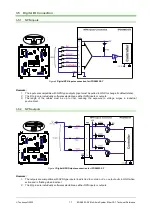
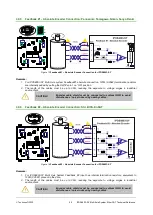
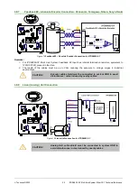
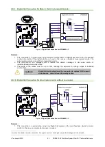
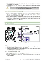
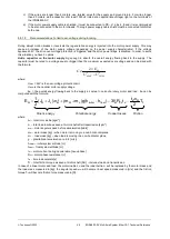
Figure 6
0-5V
Analog inputs connection for iPOS4803-SY
Remarks:
1. The analog input range is configurable by software: 16bit ±10V or 12-bit 0-5V: Reference, Feedback or
general purpose input.
2. The length of the cables must be up to 30m, reducing the exposure to voltage surges in industrial
environment.
3.6.1.1
Recommendation for wiring
a) If the analogue signal source is single-ended, use a 2-wire twisted shielded cable as follows: 1
st
wire
connects the live signal to the drive input; 2
nd
wire connects the source ground to the drive ground; shield will
be connected to the drive ground terminal.
b) If the analogue signal source is differential and the signal source ground is isolated from the drive GND, use
a 2-wire twisted shielded cable as follows: 1
st
wire connects the source plus (positive, in-phase) to the drive
analogue input; 2
nd
wire connects the source minus (negative, out-of-phase) to the drive ground (GND).
Shield is connected only at the drive side, to the drive PE, and is left unconnected at the source side.
c) If the analogue signal source is differential and the signal source ground is common with the drive GND, use
a 2-wire shielded cable as follows: 1
st
wire connects the source plus (positive, in-phase) to the drive
analogue input; 2
nd
wire connects the source ground to the drive ground (GND); shield is connected only at
the drive side, to the drive PE, and is left unconnected at the source side. The source minus (negative, out-
of-phase) output remains unconnected.


